
Supercritical CO2 combined heat and power generation system and method integrated with multi-stage compression heat pump

A cogeneration and supercritical technology, which is applied in heat recovery systems, energy-saving heating/cooling, energy industry, etc., can solve the problems of low utilization level of waste heat at the cold end, low COP of heat pump, and increased power consumption of heat pump, so as to improve waste heat The effect of utilization level, improving COP and reducing heat exchange temperature difference

Pending Publication Date: 2022-07-08
XIAN THERMAL POWER RES INST CO LTD
View PDF0 Cites 0 Cited by
  • Summary
  • Abstract
  • Description
  • Claims
  • Application Information

AI Technical Summary

Problems solved by technology

Although the working fluid temperature at the inlet of the precooler is relatively high, the outlet temperature is relatively low at about 32°C
In order to fully recover the waste heat at the cold end, the evaporation temperature of the single-stage heat pump needs to be lower than the inlet working fluid temperature of the precooler, so that the evaporation temperature is lower and the COP of the heat pump is lower, resulting in increased power consumption of the heat pump and a lower utilization level of waste heat at the cold end

Method used


Image

  • Supercritical CO2 combined heat and power generation system and method integrated with multi-stage compression heat pump
  • Supercritical CO2 combined heat and power generation system and method integrated with multi-stage compression heat pump
  • Supercritical CO2 combined heat and power generation system and method integrated with multi-stage compression heat pump

Examples


Embodiment Construction

[0026] The present invention will be further described in detail below in conjunction with specific embodiments, which are to explain rather than limit the present invention.

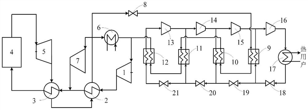
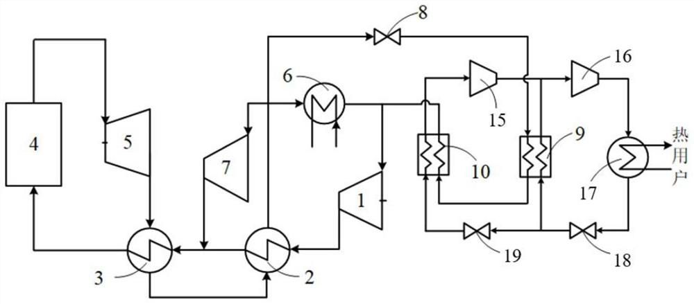
[0027] A Supercritical CO2 Integrated Multistage Compression Heat Pump 2 Combined heat and power systems such as figure 1 As shown, including supercritical carbon dioxide cycle power generation system and heating system; including main compressor 1, low temperature regenerator 2, high temperature regenerator 3, boiler 4, turbine 5, precooler 6, auxiliary compressor 7, Flow regulating valve 8, first stage evaporator 9, second stage evaporator 10, third stage evaporator 11, fourth stage evaporator 12, fourth stage compressor 13, third stage compressor 14, second stage Compressor 15, first stage compressor 16, condenser 17, first stage throttle valve 18, second stage throttle valve 19, third stage throttle valve 20, fourth stage throttle valve 21,

[0028] The supercritical carbon dioxide cycle power gen...


PUM


Abstract

The invention provides a supercritical CO2 combined heat and power generation system and method integrated with a multi-stage compression heat pump, the supercritical CO2 combined heat and power generation system comprises a supercritical CO2 cycle power generation system, an outlet of a main compressor is sequentially communicated with a low-temperature heat regenerator, a high-temperature heat regenerator, a boiler and a turbine, and an outlet of a precooler is communicated with an inlet of the main compressor; an inlet of the auxiliary compressor communicates with a hot side outlet of the low-temperature regenerator, and an outlet of the auxiliary compressor communicates with a cold side outlet of the low-temperature regenerator. The multi-stage compression heat pump assemblies in the heat supply system are connected in series stage by stage, the hot ends of the multi-stage compression heat pump assemblies communicate with the supercritical carbon dioxide cycle power generation system, and the cold ends of the multi-stage compression heat pump assemblies communicate with the condenser. The multi-stage compression heat pump is adopted to recover waste heat of the cold end, so that irreversible loss of heat transfer is greatly reduced, quality-divided gradient utilization of energy is achieved, and the energy utilization efficiency of the system is greatly improved. In addition, thermoelectricity decoupling can be achieved, and the operation flexibility of the system is greatly improved.

Description

technical field [0001] The invention belongs to the technical field of power generation, and relates to a supercritical CO2 integrated multi-stage compression heat pump 2 Combined heat and power systems and methods. Background technique [0002] With the advantages of high thermal efficiency, compact structure, low investment and low operation and maintenance costs, the supercritical carbon dioxide power cycle system is expected to replace the traditional steam Rankine cycle and greatly improve the power generation efficiency of coal-fired units, thereby reducing pollutants and carbon dioxide emissions. However, the heat release temperature at the cold end of the supercritical carbon dioxide power cycle power generation system is relatively high, and the temperature of the working fluid at the inlet of the cooler is above 90 °C. This part of the heat is taken away by the cooling medium and released into the environment, causing a large amount of energy loss. In order to red...

Claims


Application Information

Patent Timeline
Patent Type & Authority Applications(China)
IPC IPC(8): F01K25/10F01K7/32F01K11/02F01K3/18F01K17/02
CPCF01K25/103F01K7/32F01K11/02F01K3/18F01K17/02Y02P80/15
Inventor 张旭伟李红智张磊蒋世希吴帅帅张一帆姚明宇
Owner XIAN THERMAL POWER RES INST CO LTD
Learn More