High-strength embedded mounting type surface-mounted magnetic gathering type hydrogen-resistant permanent magnet motor rotor
A permanent magnet motor, high-strength technology, applied in the direction of magnetic circuit rotating parts, magnetic circuit shape/style/structure, magnetic circuit, etc., can solve the problem of air gap length sensitivity, difficult design, damage to the surface coating of magnetic steel, etc. problems, to achieve the effects of reducing the risk of stress concentration, improving the magnetic performance, and improving the strength of the rotor
- Summary
- Abstract
- Description
- Claims
- Application Information
AI Technical Summary
Problems solved by technology
Method used
Image

Examples
Embodiment 1
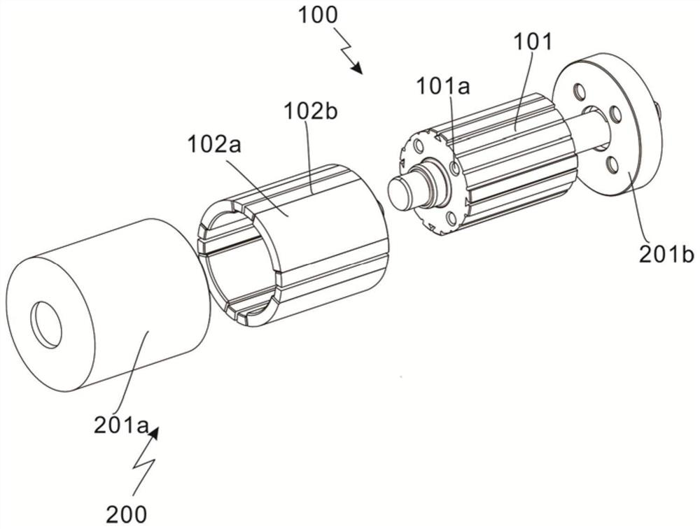
[0034] refer to Figure 1 to Figure 2 , which is the first embodiment of the present invention, which provides a high-strength embedded-mounted surface-mounted magnetic-focusing type hydrogen-resistant permanent magnet motor rotor, including a main body assembly 100, including an integrated rotor core 101, a rotor magnetic pole permanent magnet The magnet 102, the permanent magnet 102 of the rotor pole is attached to the outside of the integrated rotor core 101;
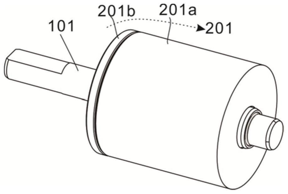
[0035] The guard assembly 200 includes a guard 201 , and the guard 201 is sleeved on the outside of the integrated rotor iron core 101 .
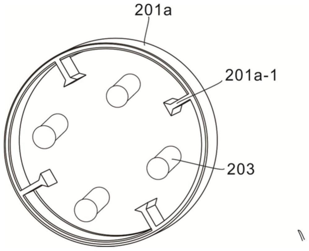
[0036] The rotor of a high-strength embedded installation type surface-mounted magnetic-gathering type hydrogen-resistant permanent magnet motor developed by the present invention is fixed on the rotor iron core 101 by fixing a special-shaped protective sleeve with a dovetail-shaped reinforcing rib 201a-1 inside, which can lift the rotor. The high-strength sheath wraps the rotor ...
Embodiment 2
[0038] refer to Figure 1 to Figure 5 , is the second embodiment of the present invention, which is different from the previous embodiment in that:
[0039] The guard 201 includes a special-shaped protective sleeve 201 a and a protective end cover 201 b .
[0040] Preferably, the special-shaped protective sleeve 201a wraps the rotor magnetic pole permanent magnet 102 and the integrated rotor iron core 101 to form an embedded structure, and the cavity formed by the special-shaped protective sleeve 201a and the integrated rotor iron core 101 is injected with magnetic steel glue inside , insert the rotor pole permanent magnets 102 into the cavity in an orderly manner, and the magnetic steel glue can closely stick the rotor pole main permanent magnet 102a and the rotor pole auxiliary permanent magnet 102b on the outside of the integrated rotor core 101, and fill the special-shaped protective sleeve The remaining gap between 201a and the cavity formed by the integrated rotor core 10...
Embodiment 3
[0049] refer to Figure 6 to Figure 11 , which is the third embodiment of the present invention, which is different from the previous two embodiments in that: a side of the protective end cover 201b is provided with a receiving hole 201b-1, and the interior of the protective end cover 201b is also provided with a transverse groove 201b-2, The transverse groove 201b-2 communicates with the receiving hole 201b-1.
[0050] Preferably, one end of the sliding rail 304 is fixedly connected to the sliding plate 301, and the other end extends toward the transverse groove 201b-2.
[0051] A rotating disk 301 is disposed outside the rotor core 101 , and a slot 302 is formed inside the rotating disk 301 , and a plurality of rotating balls 303 are accommodated in the slot 302 .
[0052] Further, when the rotor rotates at a high speed, the rotor drives the rotating disk 301 to rotate, and the rotating balls in the slot 302 of the rotating disk 301 rotate with the rotation of the rotating ...
PUM
 Abstract
Description
Claims
Application Information
 - R&D
- Intellectual Property
- Life Sciences
- Materials
- Tech Scout
- Unparalleled Data Quality
- Higher Quality Content
- 60% Fewer Hallucinations
Browse by: Latest US Patents, China's latest patents, Technical Efficacy Thesaurus, Application Domain, Technology Topic, Popular Technical Reports.
© 2025 PatSnap. All rights reserved.Legal|Privacy policy|Modern Slavery Act Transparency Statement|Sitemap|About US| Contact US: help@patsnap.com