
Miniature wearable photoacoustic signal acquisition system

A photoacoustic signal and acquisition system technology, applied in medical science, diagnosis, diagnostic recording/measurement, etc., can solve the problems of being easily submerged by noise, low amplitude of photoacoustic signal, and insufficient acquisition effect.

Pending Publication Date: 2022-07-12
UNIV OF ELECTRONIC SCI & TECH OF CHINA
View PDF8 Cites 0 Cited by
  • Summary
  • Abstract
  • Description
  • Claims
  • Application Information

AI Technical Summary

Problems solved by technology

[0002] The photoacoustic effect is to use pulsed laser as excitation. When the pulsed laser irradiates the tissue, the tissue absorbs the light energy and converts it into heat energy, then generates thermal expansion, and finally propagates the signal in the form of ultrasonic wave, that is, the photoacoustic signal; photoacoustic signal The signal is received by the ultrasonic transducer through the ultrasonic coupling dose, and the analog signal is converted into a digital signal through a high-speed acquisition card and stored on the computer; due to the photoacoustic effect, the frequency band of the photoacoustic signal generated by the centimeter-level absorber is about 20-300kHz, the frequency band of the photoacoustic signal generated by the millimeter-scale absorber is about 70kHz-2.5MHz, the frequency band of the photoacoustic signal generated by the micron-scale absorber is about 400kHz-20MHz, and the human blood vessel tissue belongs to the micron-scale Therefore, the frequency of the photoacoustic signal excited by the absorption is generally between hundreds of kHz and tens of MHz. In addition, the signal amplitude is generally at the microvolt level, and the duration of a signal pulse is at the millisecond or even microsecond level. The amplitude of the photoacoustic signal is low, and it is easy to be submerged by noise. However, the existing photoacoustic signal acquisition system cannot amplify the tiny photoacoustic signal, and the acquisition effect is insufficient.

Method used


Image

  • Miniature wearable photoacoustic signal acquisition system
  • Miniature wearable photoacoustic signal acquisition system
  • Miniature wearable photoacoustic signal acquisition system

Examples


Embodiment Construction

[0036] The following describes in detail the embodiments of the present invention, examples of which are illustrated in the accompanying drawings, wherein the same or similar reference numerals refer to the same or similar elements or elements having the same or similar functions throughout. The embodiments described below with reference to the accompanying drawings are exemplary, and are intended to explain the present invention and should not be construed as limiting the present invention.

[0037] In the description of the present invention, it should be understood that the terms "length", "width", "upper", "lower", "front", "rear", "left", "right", "vertical", The orientations or positional relationships indicated by "horizontal", "top", "bottom", "inside", "outside", etc. are based on the orientations or positional relationships shown in the accompanying drawings, which are only for the convenience of describing the present invention and simplifying the description, rather...


PUM


Abstract

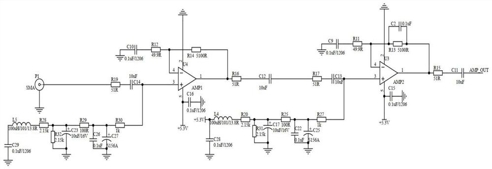
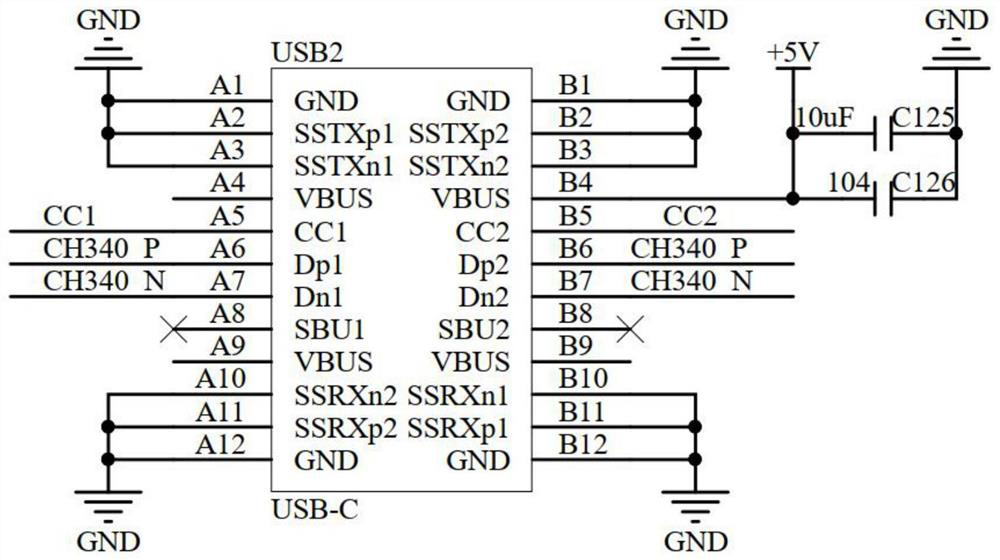
The invention relates to the field of photoacoustic technology, in particular to a miniature wearable photoacoustic signal acquisition system, which comprises a first voltage stabilizing circuit, an amplifying circuit, a second voltage stabilizing circuit, an analog-to-digital conversion circuit, an FPGA (Field Programmable Gate Array) main control circuit, a third voltage stabilizing circuit and a serial port output circuit, after an ultrasonic pulse signal of the ultrasonic probe is amplified by the amplifying circuit, the ultrasonic pulse signal is converted into a 12-bit digital signal by the analog-to-digital conversion circuit, the FPGA main control circuit provides a 65MHz clock rising edge each time, the analog-to-digital conversion circuit carries out data conversion once to obtain a primary signal, and the amplified analog signal can be continuously subjected to analog-to-digital conversion by continuously providing a 65MHz clock, so that the analog-to-digital conversion is realized. And then the data is output through the serial port output circuit, so that the photoacoustic signal can be amplified when the photoacoustic signal is collected, and the amplitude of the photoacoustic signal is improved.

Description

technical field [0001] The invention relates to the field of photoacoustic technology, in particular to a miniature wearable photoacoustic signal acquisition system. Background technique [0002] The photoacoustic effect uses a pulsed laser as excitation. When the pulsed laser irradiates the tissue, the tissue absorbs light energy and converts it into heat energy, followed by thermal expansion, and finally propagates the signal outward in the form of ultrasonic waves, that is, the photoacoustic signal; The signal is received by the ultrasonic transducer through the ultrasonic coupling dose, and the analog signal is converted into a digital signal through the high-speed acquisition card and stored on the computer; due to the photoacoustic effect, the frequency band of the photoacoustic signal generated by the centimeter-scale absorber is about It is 20-300kHz, the frequency band of the photoacoustic signal generated by the millimeter-scale absorber is about 70kHz-2.5MHz, the ...

Claims


Application Information

Patent Timeline
IPC IPC(8): A61B5/00
CPCA61B5/0095A61B5/0033
Inventor 黄逸轩吕治宽
Owner UNIV OF ELECTRONIC SCI & TECH OF CHINA
Learn More