
Blowing and sucking type carbon dioxide adsorption and trapping reaction device

A carbon dioxide and reaction device technology, applied in chemical instruments and methods, separation methods, products, etc., can solve problems such as low efficiency and complex structure, achieve high concentration, simplify system layout, and reduce investment costs and operating costs.

Pending Publication Date: 2022-07-12
HARBIN BOILER
View PDF0 Cites 0 Cited by
  • Summary
  • Abstract
  • Description
  • Claims
  • Application Information

AI Technical Summary

Problems solved by technology

[0003] The purpose of the patent of the present invention: In order to solve the problem of complex structure and low efficiency of the existing carbon capture equipment, the present invention proposes a blowing-suction carbon dioxide adsorption and capture reaction device

Method used


Image

  • Blowing and sucking type carbon dioxide adsorption and trapping reaction device
  • Blowing and sucking type carbon dioxide adsorption and trapping reaction device

Examples


specific Embodiment approach 1

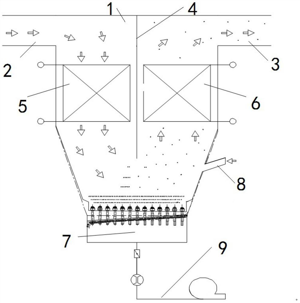
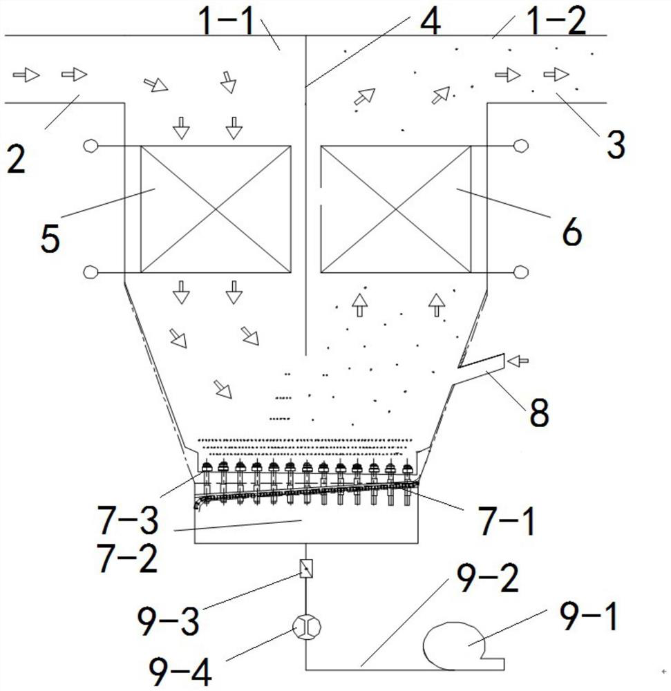
[0027] Embodiment 1: A blowing and suction carbon dioxide adsorption and capture reaction device, which includes a flue gas circulation flue 1, a high-temperature flue gas inlet flue 2, a high-temperature flue gas outlet flue 3, an intermediate partition wall 4, and a front flue. Heat exchanger 5, rear flue heat exchanger 6, air distribution fluidization device 7, carbon dioxide adsorbent supplementary pipeline 8 and fluidized air conveying system 9;

[0028] The flue gas circulation flue 1 is in the shape of a funnel with a seal at the top. The air distribution fluidization device 7 is arranged at the bottom of the flue gas circulation flue 1. The fluidized air conveying system 9 is communicated with the air distribution fluidization device 7. The partition wall 4 is arranged on the inner side of the flue gas circulation flue 1, the top and both ends of the intermediate partition wall 4 are fixedly connected with the flue gas circulation flue 1, and the intermediate partition ...

specific Embodiment approach 2

[0030] Embodiment 2: A blow-suction type carbon dioxide adsorption and capture reaction device, the air distribution fluidization device 7 includes an air distribution plate 7-1, a fluidized air chamber 7-2 and a plurality of air caps 7-3;

[0031] The fluidized air chamber 7-2 is fixed at the bottom of the flue gas circulation flue 1, and the bottom of the fluidized air chamber 7-2 is sealed, and the air distribution plate 7-1 is fixed on the fluidized air chamber 7- 2, a plurality of air caps 7-3 are arranged on the air distribution plate 7-1.

[0032] In this embodiment: the air distribution fluidization device is mainly composed of a wind cap and an air distribution plate, the fluidized air chamber provides stable fluidized air for the air distribution plate, and the fluidized air conveying system is composed of a fan, a flow meter and a damper; The outlet chamber is the main capture and reaction area for calcium-based adsorbent to capture carbon dioxide in flue gas.

[0...

specific Embodiment approach 3

[0034] Embodiment 3: A blow-suction type carbon dioxide adsorption and capture reaction device, the fluidized wind conveying system 9 includes a fluidizing fan 9-1 and a conveying pipeline 9-2;

[0035] The inlet end of the conveying pipeline 9-2 is connected with the fluidizing fan 9-1, and the outlet end of the conveying pipeline 9-2 is connected with the bottom of the fluidizing air chamber 7-2.

[0036] Other embodiments are the same as the second embodiment.


PUM


Abstract

The invention relates to the field of carbon dioxide adsorption and capture reaction, in particular to a blowing and sucking type carbon dioxide adsorption and capture reaction device, and aims to solve the problems that existing carbon capture equipment is complex in structure and low in efficiency and does not meet development requirements. The air distribution fluidizing device is arranged at the bottom of the flue gas circulation flue, the fluidizing air conveying system is communicated with the air distribution fluidizing device, the middle partition wall is arranged on the inner side of the flue gas circulation flue, and the flue gas circulation flue is divided into a flue gas inlet cavity and a flue gas outlet cavity by the middle partition wall; the high-temperature flue gas inlet flue is communicated with a flue gas inlet cavity internally provided with a front flue heat exchanger, the high-temperature flue gas outlet flue is communicated with a flue gas outlet cavity internally provided with a rear flue heat exchanger, and the carbon dioxide adsorbent supplementing pipeline is arranged on the side portion of the lower end of the flue gas outlet cavity. By using the adsorbent as a carbon dioxide adsorbent, the system arrangement is simplified, and the investment cost and the operation cost are reduced.

Description

technical field [0001] The invention relates to the field of carbon dioxide adsorption and capture reaction, in particular to a blow-suction type carbon dioxide adsorption and capture reaction device. Background technique [0002] The carbon dioxide produced in the production process of thermal power plants, cement, papermaking, industrial boilers and kilns accounts for a large proportion of the total carbon dioxide emissions in my country. The carbon capture has a profound impact on the realization of the dual carbon goal in my country. The existing carbon capture equipment has a complex structure and low efficiency, which does not meet the development needs. SUMMARY OF THE INVENTION [0003] The purpose of the patent of the present invention: In order to solve the problems of complex structure and low efficiency of the existing carbon capture equipment, the present invention proposes a blow-suction type carbon dioxide adsorption and capture reaction device. [0004] The ...

Claims


Application Information

Patent Timeline
IPC IPC(8): B01D53/04
CPCB01D53/0438B01D53/0407B01D2258/0283B01D2253/1124B01D2258/0233B01D2257/504B01D2259/40043Y02P20/151
Inventor 王德华孙向文宋宝军姜孝国王永杰谷金宇何明月王瑀姜雪蔡健陈鹏张钧赵桂锋杨勇
Owner HARBIN BOILER
Learn More