Eureka AIR delivers breakthrough ideas for toughest innovation challenges, trusted by R&D personnel around the world.

Spacecraft high-voltage distribution power and current sampling circuit

A high-voltage power distribution and current sampling technology, which is applied to the conversion device for measuring current/voltage, output power, and the power supply system of space vehicles, etc., can solve the problem that the drive circuit does not have the current acquisition function and the reliability of the high-voltage power supply circuit is low. , The circuit does not have the telemetry acquisition function, etc., to achieve the effect of improving safety and reliability, occupying a small space and light weight

Pending Publication Date: 2022-07-12
SHANGHAI SATELLITE ENG INST
View PDF2 Cites 0 Cited by
  • Summary
  • Abstract
  • Description
  • Claims
  • Application Information

AI Technical Summary

Problems solved by technology

[0003] In the Chinese patent document with the notification number CN107809231B, a power field effect drive control and state acquisition circuit and method of the space-borne heater are disclosed. This patent document uses a triode to drive the field effect tube on and off. The disadvantage is that the drive circuit is complicated. The reliability of the circuit is low in the high-voltage power supply circuit, and the drive circuit does not have the function of current acquisition
[0004] In the Chinese patent document with the publication number CN101453117A, a startup surge current suppression device suitable for the power supply and distribution system of spacecraft is disclosed. The tube circuit controls the negative terminal of the busbar to be turned on slowly to achieve the purpose of suppressing the start-up surge current. Its disadvantage is that in the application scenario of high-voltage power distribution, due to the limitations of relay performance, volume, and weight, it is no longer suitable for Spacecraft power distribution control, and the above circuit does not have the function of telemetry acquisition

Method used


Image

  • Spacecraft high-voltage distribution power and current sampling circuit

Examples


Embodiment Construction

[0020] The present invention will be described in detail below with reference to specific embodiments. The following examples will help those skilled in the art to further understand the present invention, but do not limit the present invention in any form. It should be noted that, for those skilled in the art, several changes and improvements can be made without departing from the inventive concept. These all belong to the protection scope of the present invention.

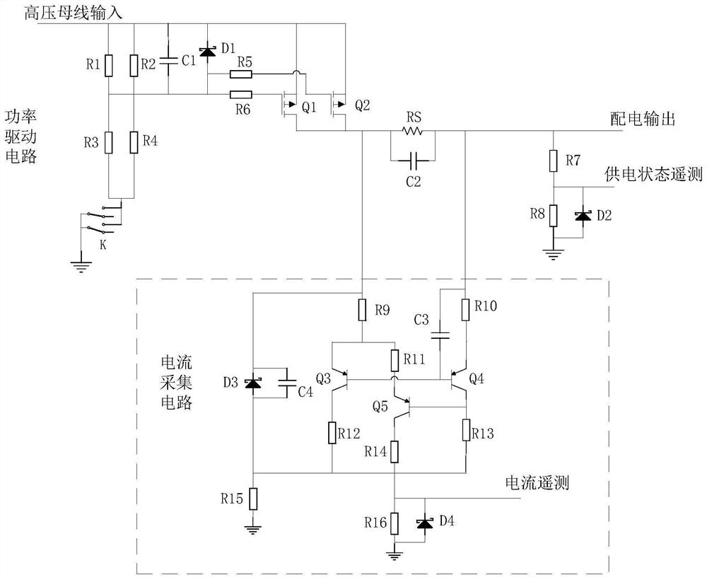
[0021] The invention discloses a high-voltage power distribution power and current sampling circuit for a spacecraft. figure 1 , including: a power drive circuit and a current collection circuit, the power drive circuit is connected with an external high-voltage bus, and the current collection circuit is connected with the power drive circuit.

[0022] The power drive circuit includes resistor R1, resistor R2, resistor R3, resistor R4, resistor R5, resistor R6, resistor R7 and resistor R8, capacitor C1, Zener d...


PUM


Abstract

The invention provides a spacecraft high-voltage distribution power and current sampling circuit which comprises a power drive circuit and a current acquisition circuit, the power drive circuit is connected with an external high-voltage bus, and the current acquisition circuit is connected with the power drive circuit. The power driving circuit realizes on-off control of a field effect transistor and has a working state acquisition function, and the current acquisition circuit is used for acquiring total current on a path when supplying power to a rear-end load so as to realize real-time monitoring of power utilization of the load. According to the invention, 0-300V wide-voltage high-power power supply control can be effectively realized through low-voltage driving, and meanwhile, functions of high-voltage power supply state monitoring and load current acquisition are realized, so that the safety and reliability of high-voltage power supply and distribution of the spacecraft are greatly improved.

Description

technical field [0001] The invention relates to a power drive and collection circuit, in particular to a high-voltage power distribution power drive and current collection circuit of a spacecraft. Background technique [0002] The high-voltage power distribution power drive circuit usually belongs to the power supply and distribution system, which is responsible for distributing electric energy to the high-power electrical equipment during the spacecraft's life cycle. It is an important part of the spacecraft. The working state of the power drive circuit directly affects the mission. success or failure. In recent years, with the development of my country's aerospace industry, the scale of spacecraft has become larger and larger, and high-voltage and high-power power distribution has become the trend of future development. In the face of high-voltage and high-power distribution requirements, the traditional relay control circuit is no longer suitable for direct control of hi...

Claims


Application Information

Patent Timeline
Patent Type & Authority Applications(China)
IPC IPC(8): H02M1/00H02M1/08H02M1/088B64G1/42G01R19/00
CPCH02M1/00H02M1/08H02M1/088B64G1/428G01R19/00
Inventor 屈炜丁锋锋宋文磊张钊吴美雯
Owner SHANGHAI SATELLITE ENG INST
Why Eureka
Eureka Blog
Learn More