Water-gas separation treatment system of breathing loop pipeline
A water-gas separation and breathing circuit technology, applied in respirator, separation method, dispersed particle separation, etc., can solve problems such as affecting the comfort of patients, insufficient removal of condensed water, and affecting the evaporation efficiency of condensed water, etc. separation effect
- Summary
- Abstract
- Description
- Claims
- Application Information
AI Technical Summary
Problems solved by technology
Method used
Image
Examples
Embodiment 1
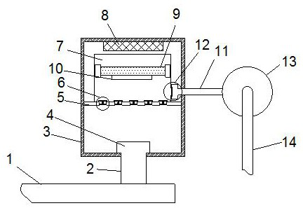
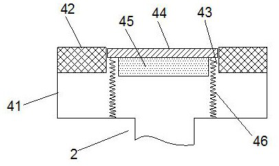
[0040] like Figure 1-2 7-8, a water-gas separation processing system of a breathing circuit pipeline, comprising an exhalation pipe 1, the expiratory pipe 1 is connected with a communication pipe 2 near the exhalation end, and the other end of the communication pipe 2 is connected with a shell The body 3, the exhalation pipe 1 is communicated with the interior of the casing 3 through the set communication pipe 2, the casing 3 is provided with a partition 5 inside, and at least one set of air guide mechanisms 6 is provided on the partition 5, A sealing cavity 7 is arranged above the partition plate 5 , an electromagnet 8 is arranged above the sealing cavity 7 , and the electromagnet 8 is connected to an AC power supply through a wire, and a magnetic plate 9 is arranged in the sealing cavity 7 The magnetic plate 9 is provided with a rubber pad on the peripheral side, and the magnetic plate 9 is sealed and slidably connected to the sealing cavity 7 through the rubber pad provide...
Embodiment 2
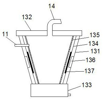
[0046] like image 3As shown, on the basis of Embodiment 1, the separation mechanism 13 includes a tapered tube 131, and the tapered tube 131 is connected to the air duct 11 at a position close to the top, and the top of the tapered tube 131 is provided with The upper cover 132, the air return pipe 14 is connected above the upper cover 132, the bottom of the tapered pipe 131 is connected with a collection box 133, and the collection box 133 is provided with a drain pipe; the inner side of the tapered pipe 131 is provided with a guide plate , the guide pipe 134, the upper end of the guide pipe 134 is connected with the upper cover 132, and the bottom end is connected with the collection box 133; the inside of the guide pipe 134 is provided with a porous pipe 135, and the porous pipe 135 There are a plurality of small holes at the beginning, the upper end of the porous tube 135 is connected with the upper cover 132 , and the bottom end is connected with the collection box 133 . ...
Embodiment 3
[0052] like Figure 4-6 As shown, on the basis of the first embodiment, the vibration mechanism 136 includes a base 1361, one end of the base 1361 is connected with the inner wall of the tapered tube 131, and the other end of the base 1361 is connected with a vibrating body 1362, The other end of the vibrating body 1362 is connected with an elastic limiting member 1363 , and the other end of the elastic limiting member 1363 is connected with the inner wall of the tapered tube 131 .
[0053] The vibrating element includes multilayer piezoelectric sheets, which are electrically connected by wires, each layer of piezoelectric sheets includes a piezoelectric ceramic sheet 1364, and a substrate 1365 is connected to one side of the piezoelectric ceramic sheet 1364. The substrate 1365 is made of an elastic metal material; the piezoelectric ceramic sheets 1364 are connected in series with an AC voltage through wires.
[0054] The elastic limiting member 1363 includes an upper fixing ...
PUM
 Abstract
Description
Claims
Application Information
 - R&D
- Intellectual Property
- Life Sciences
- Materials
- Tech Scout
- Unparalleled Data Quality
- Higher Quality Content
- 60% Fewer Hallucinations
Browse by: Latest US Patents, China's latest patents, Technical Efficacy Thesaurus, Application Domain, Technology Topic, Popular Technical Reports.
© 2025 PatSnap. All rights reserved.Legal|Privacy policy|Modern Slavery Act Transparency Statement|Sitemap|About US| Contact US: help@patsnap.com


