Methylsiloxane cracking tail gas purification treatment system and treatment method

A methylsiloxane and tail gas purification technology, which is applied in chemical instruments and methods, separation methods, and dispersed particle separation, can solve the problems of vacuum pump operation influence, gas VOC exceeding the standard, etc., and achieve improved operation stability, extended life, The effect of reducing production costs

Pending Publication Date: 2022-07-15
合盛硅业(泸州)有限公司
5 Cites 0 Cited by

AI-Extracted Technical Summary

Problems solved by technology

This not only affects the operation of the vacuum pump, but also causes a large amount o...

Abstract

The invention relates to the technical field of tail gas purification treatment, and provides a methylsiloxane cracking tail gas purification treatment system which comprises an absorption liquid buffer tank, an absorption liquid circulating pump, an absorption liquid condenser, a gas-liquid separator and a first vacuum pump, the absorption liquid buffer tank, the absorption liquid circulating pump, the absorption liquid condenser and the gas-liquid separator are sequentially communicated to form a closed loop, and the absorption liquid buffer tank and the first vacuum pump form a circulating loop; the methylsiloxane cracking tail gas purification treatment system provided by the invention has the following advantages: 1, D3 which is not condensed can be effectively absorbed, so that the recycling rate of methylsiloxane is increased, and the production cost is reduced; 2, as the content of D3 entering the vacuum pump is reduced, the service life of the vacuum pump is prolonged; 3, the D3 is absorbed at the front end of the vacuum pump, so that the flowing path of the D3 is shortened, and the operation stability of the system is improved; and 4, the content of D3 released into the atmosphere is reduced, and the emission amount of VOC in a factory is controlled.

Application Domain

Technology Topic

Image

  • Methylsiloxane cracking tail gas purification treatment system and treatment method

Examples

  • Experimental program(2)

Example Embodiment

[0027] Example 1
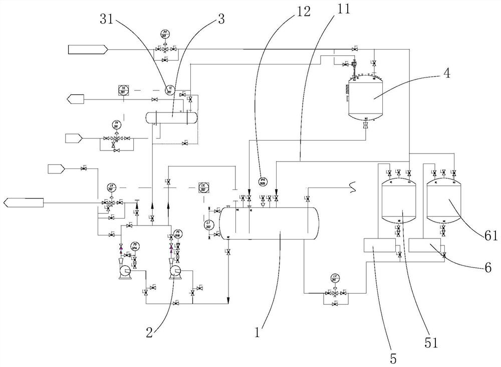
[0028] like figure 1 As shown, this embodiment provides a methylsiloxane pyrolysis tail gas purification treatment system, including an absorption liquid buffer tank 1, an absorption liquid circulation pump 2, an absorption liquid condenser 3, a gas-liquid separator 4 and a first vacuum pump 5 , the absorption liquid buffer tank 1, the absorption liquid circulating pump 2, the absorption liquid condenser 3 and the gas-liquid separator 4 are connected in turn to form a closed loop, the absorption liquid buffer tank 1 and the first vacuum pump 5 form a circulation loop, and the first vacuum pump 5 and the absorption liquid A first vacuum pump buffer tank 51 is arranged between the liquid buffer tank 1, a balance pipe 11 is arranged between the absorption liquid buffer tank 1 and the first vacuum pump 5, and also includes a second vacuum pump 6, the second vacuum pump 6 and the first vacuum pump 5 In parallel, a second vacuum pump buffer tank 61 is arranged between the second vacuum pump 6 and the absorption liquid buffer tank 1 , a pressure gauge 12 is arranged at the absorption liquid buffer tank 1 , and a thermometer 31 is arranged at the absorption liquid condenser 3 .

Example Embodiment

[0029] Example 2
[0030] This embodiment provides a method for purifying and treating methylsiloxane cracking tail gas, that is, a method for using the methylsiloxane cracking tail gas purification and treatment system provided in Example 1, as follows:
[0031] In the process of use, it is necessary to inject the absorption liquid (D in the absorption liquid) into the absorption liquid buffer tank in advance. 5 When the liquid level of the absorption liquid buffer tank reaches 60%, start the absorption liquid circulation pump to circulate the system, and the absorption liquid flows through the absorption liquid condenser and gas-liquid separator, and finally returns to the absorption liquid liquid buffer tank. After normal circulation, the pressure of the absorption liquid buffer tank is pumped to a negative pressure of more than 70kPa through the balance pipe at the top of the absorption liquid buffer tank. After the pressure reaches the condition, the vacuum line of the methylsiloxane cracking system is slowly merged into the tail gas absorption system. . In the process of circulating absorption, it is necessary to ensure that the outlet temperature of the absorption liquid condenser is between 30-40 °C, and the absorption liquid in the absorption liquid buffer tank is regularly sampled for analysis. 5 When the content is less than 50%, it is necessary to replace the absorbing liquid in time to prevent the 4 The content is too high, causing the absorption liquid to block in the condenser or other locations. In addition, it is necessary to ensure that the circulation volume of the absorption liquid is sufficient to absorb the pyrolysis tail gas, and the minimum circulation volume is not less than 20m3/h. If the circulation volume is too low, it is necessary to check whether the absorption liquid is blocked by crystallization.

PUM

no PUM

Description & Claims & Application Information

We can also present the details of the Description, Claims and Application information to help users get a comprehensive understanding of the technical details of the patent, such as background art, summary of invention, brief description of drawings, description of embodiments, and other original content. On the other hand, users can also determine the specific scope of protection of the technology through the list of claims; as well as understand the changes in the life cycle of the technology with the presentation of the patent timeline. Login to view more.

Similar technology patents

Process for recycling and collecting open residual ore

InactiveCN105971610AScientific and reasonable collection processImprove recycling ratesUnderground miningSurface miningGeological explorationMaterials science
Owner:安徽金联地矿科技有限公司

Repairing process of radial tyre of passenger car

InactiveCN103465484AImprove recycling ratesEnsure safetyRemanufacturingRadial tire
Owner:无锡翼龙航空设备有限公司

Classification and recommendation of technical efficacy words

  • Improve recycling rates
  • Reduce manufacturing cost
Why Eureka
Try Eureka