Control method of loop heat pipe

A technology of loop heat pipe and control method, which is applied in the direction of indirect heat exchangers, space navigation equipment, lighting and heating equipment, etc., which can solve the problems of component damage, high cost, and low heat exchange efficiency of components, and achieve heat transfer distance The effect of lifting, light weight, and improving heat dissipation efficiency

Inactive Publication Date: 2022-07-15
SHANDONG UNIV
View PDF0 Cites 0 Cited by
  • Summary
  • Abstract
  • Description
  • Claims
  • Application Information

AI Technical Summary

Problems solved by technology

[0007] The current loop heat pipe, evaporator and condenser all have insulation problems. Once the temperature is too low, the heat exchange efficiency of the components will be too low or the components will be damaged.
Therefore, it is necessary to set up insulation equipment, but the current insulation equipment structure is responsible and the cost is too high

Method used


Image

  • Control method of loop heat pipe
  • Control method of loop heat pipe
  • Control method of loop heat pipe

Examples


Embodiment Construction

[0037] The specific embodiments of the present invention will be described in detail below with reference to the accompanying drawings.

[0038] In this article, if there are no special instructions, when it comes to formulas, " / " means division, and "×" and "*" mean multiplication.

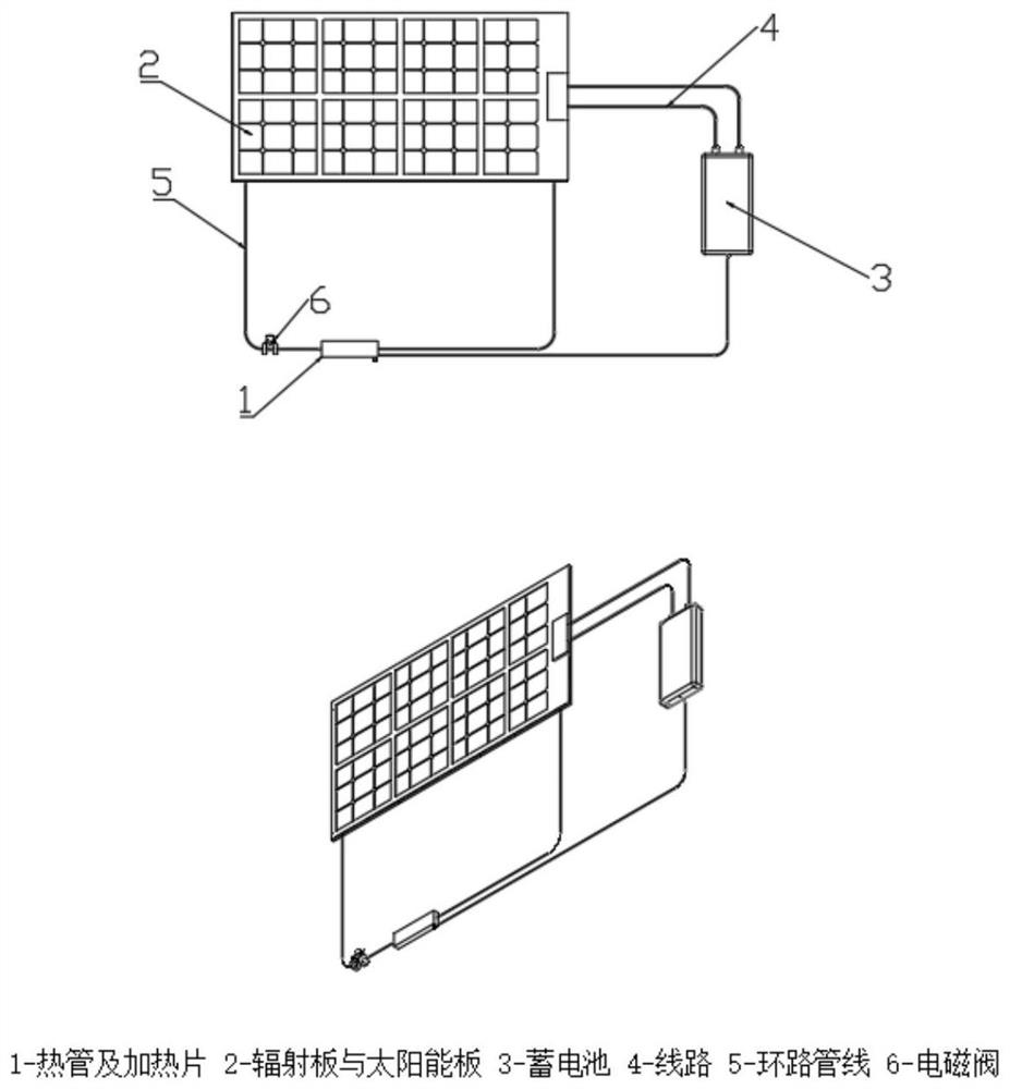
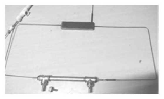
[0039] A loop heat pipe radiator composite thermal control device, such as figure 1 shown. The system includes an evaporating end 1 of a flat loop heat pipe, a ceramic heating sheet (closely attached to the evaporating end of the flat loop heat pipe), a radiant plate (a condensing end of the flat loop heat pipe) 2, a solar panel (closely attached to the evaporating end of the flat loop heat pipe) Radiant panel outer surface), battery 3, line 4, evaporation loop line 5, solenoid valve 6. Among them, the ceramic heating plate is attached to the top of the heat dissipation component; the evaporating end 1 of the flat-plate loop heat pipe is closely attached to the ceramic heating plate, and the co...


PUM


Abstract

According to the control method of the loop heat pipe, when the temperature sensor on the surface of the heat dissipation component detects that the temperature of the heat dissipation component is too high, the electromagnetic valve is automatically opened, the loop heat pipe starts to work, and heat dissipation is conducted on the heat dissipation component through the loop heat dissipation effect of the heat pipe. Firstly, a heat dissipation component transmits heat to an evaporation end of a loop heat pipe on the surface of the heat dissipation component, and a liquid working medium in the evaporation end absorbs heat and is gasified to generate power for pushing the working medium to circulate; the generated steam working medium is collected and heated in a steam channel on the surface of the capillary core, and flows into a radiator through a steam pipeline; after sensible heat and latent heat of superheated steam are dissipated in the radiator through radiation, the superheated steam is finally condensed into liquid and flows back under the action of capillary suction force, and circulation is repeated. A heat pipe radiator heat dissipation system and a solar heating system are creatively combined, and the zero-energy-consumption heat dissipation and heat preservation effects can be integrally achieved.

Description

technical field [0001] The invention belongs to the field of loop heat pipes, in particular to a control method of a loop heat pipe, and belongs to the field of F28D15 heat pipes. Background technique [0002] With the rapid development of modern society and economy, human beings have an increasing demand for energy. However, the reserves of traditional energy sources such as coal, oil, and natural gas are constantly decreasing and becoming increasingly scarce, resulting in rising prices. At the same time, the environmental pollution caused by conventional fossil fuels is also becoming more and more serious, which greatly restricts the development of society and the improvement of the quality of human life. . The energy problem has become one of the most prominent problems in the contemporary world. Therefore, the search for new energy sources, especially non-polluting clean energy sources, has become a research hotspot. [0003] Solar energy is an inexhaustible clean ene...

Claims


Application Information

Patent Timeline
Patent Type & Authority Applications(China)
IPC IPC(8): F28D15/02F28D15/04F28D15/06
CPCF28D15/0266F28D15/046F28D15/06F28D15/043
Inventor 郭春生逯晓康薛丽红杨沛东李蒸马军韩卓晟刘百川
Owner SHANDONG UNIV
Why Eureka
Try Eureka