
Power battery system, electric vehicle and design method

A technology of power battery and design method, which is applied in the direction of secondary battery, battery pack components, secondary battery repair/maintenance, etc., and can solve the problems of easy damage of battery cells, time-consuming and labor-intensive, affecting the weight and cost of the whole vehicle, etc.

Pending Publication Date: 2022-07-15
CHINA FIRST AUTOMOBILE
View PDF0 Cites 1 Cited by
  • Summary
  • Abstract
  • Description
  • Claims
  • Application Information

AI Technical Summary

Problems solved by technology

[0002] The traditional new energy power battery assembly, DC / DC, and charger are arranged in a dispersed manner, and the electrical connection between each component is realized through a high-voltage wire harness, which causes power loss and affects the weight and cost of the vehicle
[0003] In the traditional power battery solution, the high-voltage power distribution unit and battery controller are built into the battery pack, which are more fragile than the battery cells. When non-energy storage components such as the high-voltage power unit and battery controller fail, the whole package needs to be disassembled for inspection and maintenance. Maintenance, time-consuming and labor-intensive, poor maintainability
[0004] At the same time, there are relatively complex high-voltage electrical connections in the package, resulting in a waste of power battery system layout space

Method used


Image

  • Power battery system, electric vehicle and design method
  • Power battery system, electric vehicle and design method
  • Power battery system, electric vehicle and design method

Examples


Embodiment 1

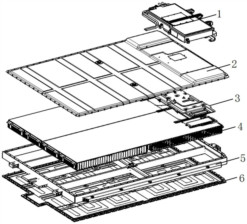
[0049] see Image 6 , a power battery system, including an energy management unit 1 and a power battery unit.

[0050] The energy management unit 1 includes a power supply device, a control device and a power distribution device.

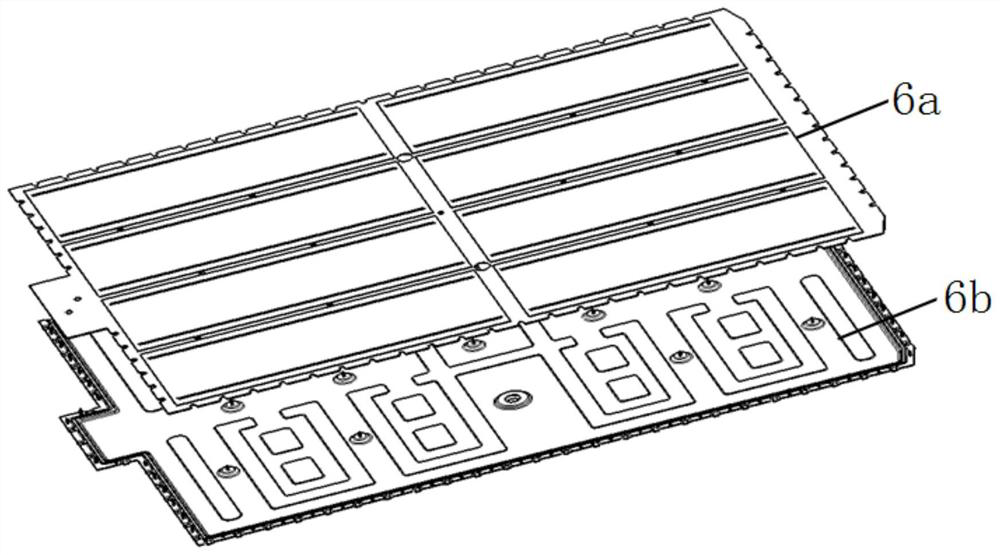
[0051] The power battery unit includes an energy storage device, a thermal management device and a sampling device.

[0052] Through the integration of the energy management unit and the power battery unit, the high integration of the high-voltage system is realized, and the weight reduction and cost reduction at the vehicle level are realized.

[0053]The power distribution device is connected in series between the high-voltage interface of the power battery unit and the DC bus interface of the electrical device; the power distribution device and the control device are connected through a low-voltage wire harness; the control device provides an action signal of the power distribution device, and the power distribution The device action realizes o...

Embodiment 2

[0062] An electric vehicle includes a power battery system, that is, an energy management unit 1 and a power battery unit. The energy management unit 1 includes a power supply device, a control device and a power distribution device. The power battery unit includes an energy storage device, a thermal management device and a sampling device. The power distribution device is connected in series between the high-voltage interface of the power battery unit and the DC bus interface of the electrical device; the power distribution device and the control device are connected through a low-voltage wire harness; the control device provides an action signal of the power distribution device, and the power distribution The device action realizes opening and closing; the energy storage device is fixed on the thermal management device; the sampling device and the energy storage device are connected by a low-voltage wire harness to realize signal transmission. The electric vehicle including...

Embodiment 3

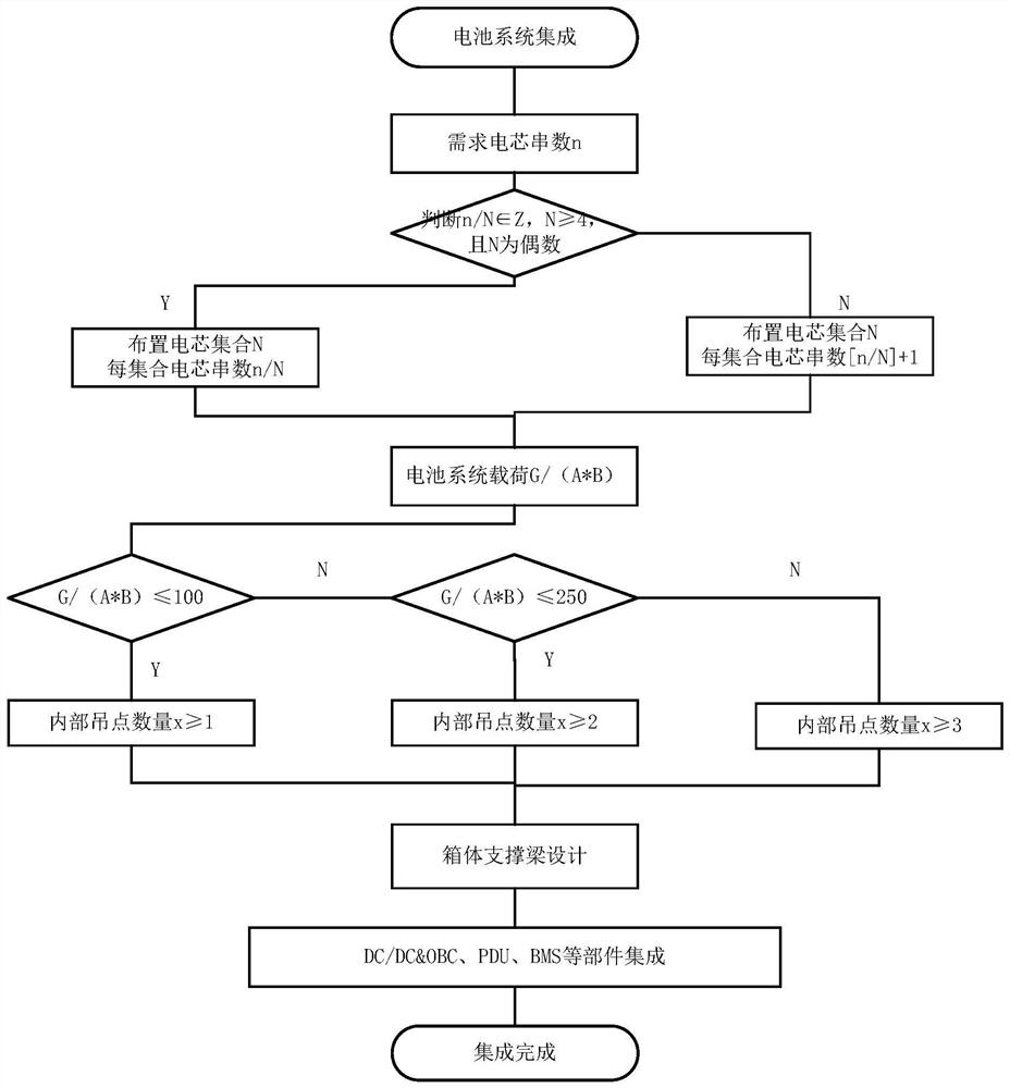
[0064] see image 3 , a design method of a power battery system for designing a power battery system, including the following steps:

[0065] Step 1, arranging the battery cell set 4 in the power battery unit;

[0066] see Figure 4 , the specific method of the step one is as follows:

[0067] Place the fuse on the output pole side of the DC bus, and set 1, 2, 3...N of battery cells to meet the following requirements:

[0068] U 1 +……+U N / 2 =U N / 2+1 +……+U N =U O / 2, where N is even and N≥4;

[0069] Among them, N is the number of cell sets; U N is the output terminal voltage of the cell set N; U O is the DC bus output voltage.

[0070] The battery cell set 4 includes a variety of battery cell forms such as square shell cells, soft-packed cells, and cylindrical cells.

[0071] The cell sets are arranged in 4 even-numbered columns, and fuses are connected in series between sets N / 2 and N / 2+1, including excitation fuses, intelligent fuses and other fuses that can inde...


PUM


Abstract

The invention belongs to the technical field of batteries, and particularly relates to a power battery system, an electric vehicle and a design method. Comprising an energy management unit and a power battery unit. The energy management unit comprises a power supply device, a control device and a power distribution device; the power battery unit comprises an energy storage device, a heat management device and a sampling device; the power distribution device is connected in series between the high-voltage interface of the power battery unit and the direct-current bus interface of the electric fitting device; the power distribution device is connected with the control device through a low-voltage wire harness; the control device provides a power distribution device action signal, and the power distribution device acts to realize on and off; the energy storage device is fixed on the heat management device; according to the invention, through integration of the energy management unit and the power battery unit, high integration of a high-voltage system is realized, and weight reduction and cost reduction of a whole vehicle level are realized.

Description

technical field [0001] The invention belongs to the technical field of batteries, in particular to a power battery system, an electric vehicle and a design method. Background technique [0002] The traditional new energy power battery assembly is distributed with DC / DC and chargers, and the electrical connection between the components is realized through the high-voltage wiring harness, which causes power loss and affects the weight and cost of the vehicle. [0003] In the traditional power battery solution, the high-voltage power distribution unit and the battery controller are built into the battery pack, which are more easily damaged than the battery cell. Maintenance is time-consuming and labor-intensive, and maintainability is poor. [0004] At the same time, there are more complex high-voltage electrical connections in the package, resulting in a waste of the layout space of the power battery system. SUMMARY OF THE INVENTION [0005] The invention provides a power ...

Claims


Application Information

Patent Timeline
Patent Type & Authority Applications(China)
IPC IPC(8): H01M10/42H01M10/613H01M10/625H01M10/6567H01M50/583
CPCH01M10/613H01M10/625H01M10/6567H01M50/583H01M10/4257H01M2010/4271Y02E60/10
Inventor 乔延涛周琪裴小娟陈永胜赵壮
Owner CHINA FIRST AUTOMOBILE
Learn More