
Device for measuring velocity and structure of detonation wave under action of liquid drops and control method thereof

A control method and technology of measuring device, which can be applied in the direction of measuring device, measuring rapid change, material excitation analysis, etc., can solve the problem of lack of sufficient understanding of the mechanism of action, etc.

Pending Publication Date: 2022-07-29
NORTHWESTERN POLYTECHNICAL UNIV
View PDF0 Cites 0 Cited by
  • Summary
  • Abstract
  • Description
  • Claims
  • Application Information

AI Technical Summary

Problems solved by technology

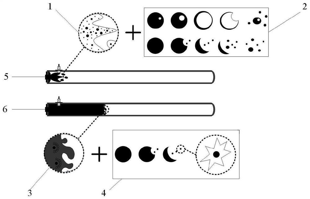
[0004] At present, due to the limitation of research methods and observation methods, there is a lack of sufficient understanding of the mechanism of liquid droplets on the local cell structure of the detonation wave, the shape of the flame surface, the thickness of the reaction zone, and the velocity of the detonation wave.

Method used


Image

  • Device for measuring velocity and structure of detonation wave under action of liquid drops and control method thereof
  • Device for measuring velocity and structure of detonation wave under action of liquid drops and control method thereof
  • Device for measuring velocity and structure of detonation wave under action of liquid drops and control method thereof

Examples


Embodiment 1

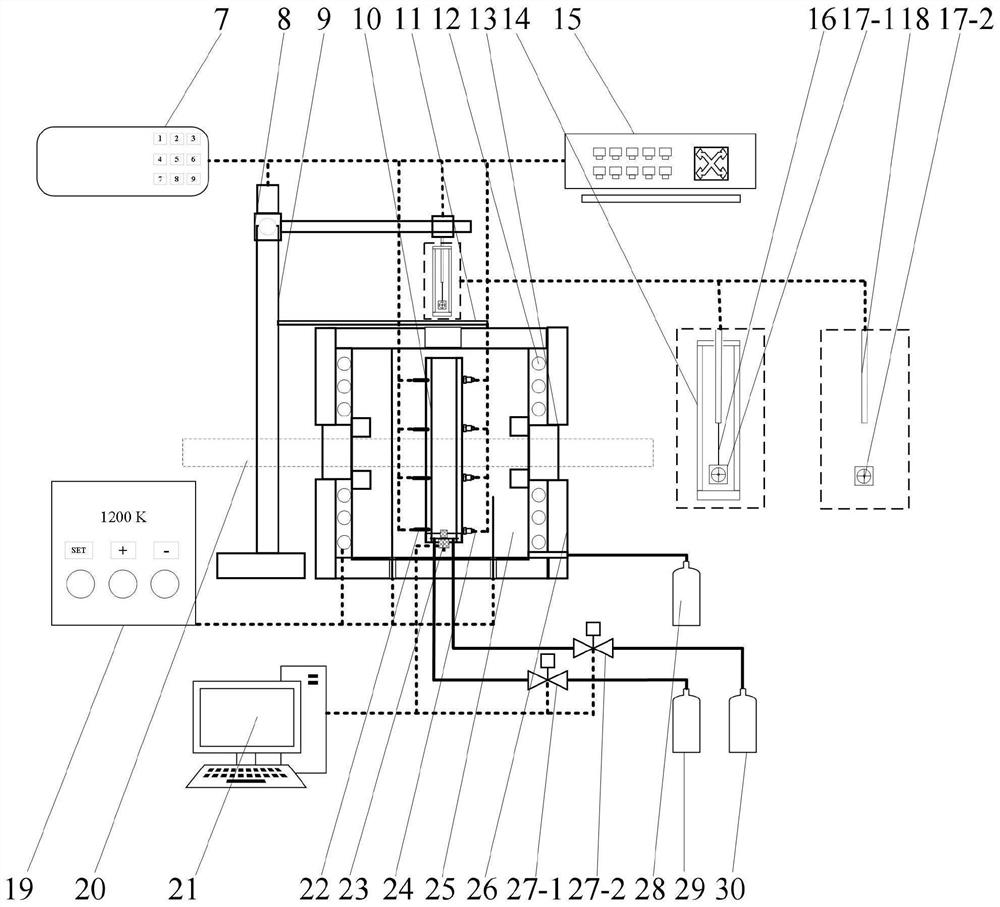
[0027] see figure 2 , In this example, a hanging droplet generation device is used, which includes a stepping motor 8 , a ball screw moving rod 9 , a heat shield 14 and a hanging wire 16 . Using the stepper motor controller 7, the stepper motor 8, and the ball screw moving rod 9, the hanging method droplet 17-1 is extended into the optical observation area of ​​the detonation tube. The depth of this penetration can be determined by the stepper motor controller 7 Take control. The droplets are heated by the heating chamber 25 with the resistance wire 12, the heating temperature is controlled by the temperature controller 19, and the thermocouple 22 monitors the temperature of the heating chamber in real time. Through the optical observation area 20, using the schlieren technique, the time when the droplet begins to microburst is measured. In the detonation tube 10, ethylene / air is used to generate a detonation wave, and the computer 21 is used to control the supply of fuel a...

Embodiment 2

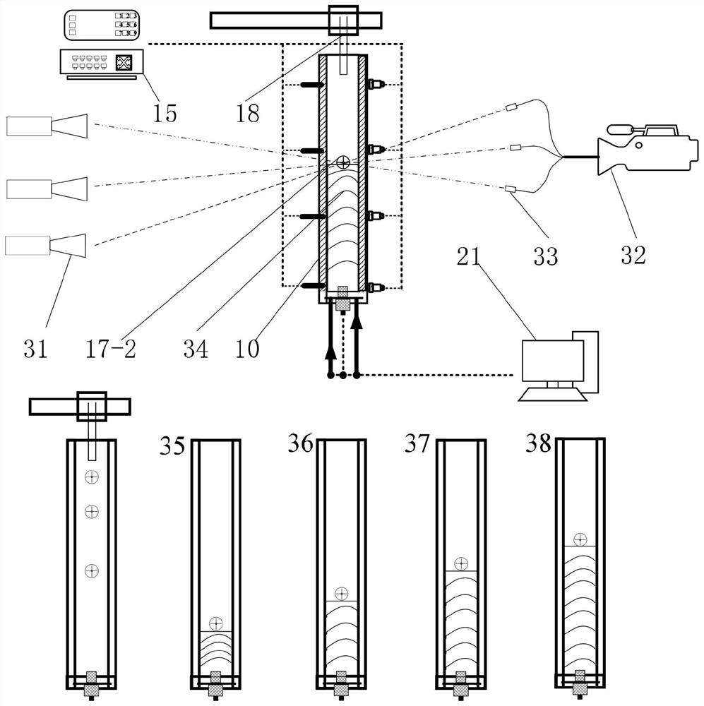
[0029] see image 3 , In this example, the droplet method 17-2 is suspended on the droplet generator 18, and the droplet method 17-2 is controlled by the droplet generator 18 to drop into the detonation tube whose initial temperature has been set 10. In the detonation tube 10, ethylene / air is used to initiate the detonation wave, and the computer 21 controls the droplet method droplet 17-2 to fall and the trigger sequence of the gas phase detonation wave 34 to start, so that the droplet and the slow combustion wave stage 35, The flame / detonation wave phases in different development stages such as the turbulent flame acceleration stage 36 , the overdrive detonation stage 37 and the stable detonation stage 38 . Use the pressure / temperature signal acquisition instrument 15 and the three-dimensional optical diagnostic system (including multiple groups of light sources 31, multi-probe optical fiber beams 33 and high-speed cameras 32) to measure the propagation velocity and cell str...


PUM


Abstract

The invention provides a device for measuring the velocity and the structure of detonation waves under the action of liquid drops and a control method of the device. The device comprises a main body heating cavity, a temperature control device, a detonation tube supply and control system, a liquid drop generation and control device, a test system and a control method. A high-precision signal generator uniformly controls the triggering time sequence of a liquid drop generator, an igniter and a high-speed camera, so that liquid drops with different micro-explosion degrees and Weber numbers interact with detonation waves at different development stages; a high-frequency pressure sensor, a high-speed shadow, a schlieren and a three-dimensional flame reconstruction technology based on stereoscopic laser-induced fluorescence are comprehensively used for measuring the propagation velocity and the structure of detonation waves at different development stages when liquid drops exist.

Description

technical field [0001] The invention relates to the fields of detonation combustion, detonation propulsion and the like, in particular to a measuring device for detonation wave velocity and structure under the action of droplets and a control method thereof. Background technique [0002] Detonation combustion is different from slow combustion combustion, which is essentially a process of realizing extremely fast chemical reactions with low entropy increase. Since the process of detonation combustion is similar to isovolumetric combustion, it has higher thermal cycle efficiency than isobaric combustion. In addition, because the leading shock wave can pre-compress the reactants, that is, the detonation wave has a better self-pressurization effect, such as When used in the engine, the supercharging components can be omitted and the structure can be simplified. Based on the above theoretical advantages, detonation combustion and detonation propulsion have become one of the curr...

Claims


Application Information

Patent Timeline
IPC IPC(8): G01L23/22G01N21/64G01N21/84
CPCG01L23/22G01L23/221G01N21/64G01N21/84G01N2021/8411
Inventor 张启斌杨锐赵明皓沙宇范玮
Owner NORTHWESTERN POLYTECHNICAL UNIV
Learn More