
Missile-borne ultrahigh-temperature flexible low-loss radio frequency coaxial cable

A radio frequency coaxial cable, ultra-high technology, applied in the direction of coaxial cable/analog cable, insulated cable, cable, etc., can solve the problem that the temperature performance of flexible low-loss cables cannot meet the requirements of use, and high-temperature-resistant cables do not have soft, low-temperature Loss, inability to apply low loss and bending requirements, etc., to achieve good electrical conductivity, strong passivation ability, and low dielectric loss

Pending Publication Date: 2022-07-29
陕西华达线缆技术有限责任公司
View PDF0 Cites 0 Cited by
  • Summary
  • Abstract
  • Description
  • Claims
  • Application Information

AI Technical Summary

Problems solved by technology

[0004] To sum up, the temperature performance of existing flexible low-loss cables cannot meet the requirements of missile-borne and radar applications with special high-temperature requirements; required environment; how to provide a radio frequency coaxial cable that can meet the high temperature requirements and have soft, low-loss functions has become a technical problem to be solved urgently by those skilled in the art

Method used


Image

  • Missile-borne ultrahigh-temperature flexible low-loss radio frequency coaxial cable

Examples


no. 1 example

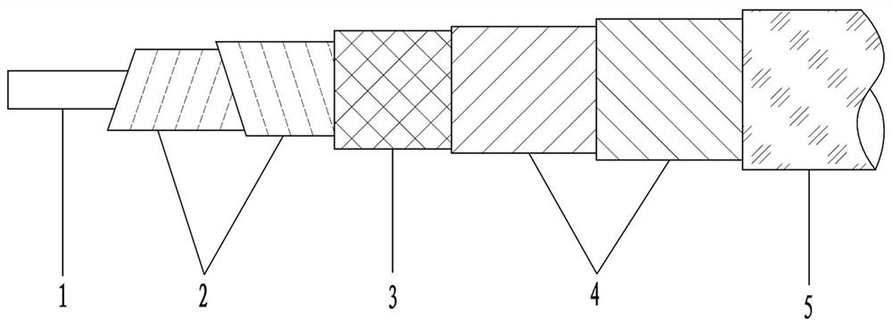
[0019] The first embodiment: as figure 1 As shown in the figure, an ultra-high temperature flexible radio frequency coaxial cable for bomb-borne use includes a conductor 1, an insulating layer 2, a shielding layer 3, a barrier layer 4 and a protective sheath arranged on the outside of the conductor 1 in turn. The conductor 1, the insulating layer 2 , the shielding layer 3, the blocking layer 4 and the protective cover 5 are all high temperature resistant materials, the protective cover 5 is a flexible material, and the insulating layer 2 is a low dielectric loss material.

[0020] The insulating layer 2 includes multiple layers of quartz fiber cloth wrapped around the outside of the conductor 1 .

[0021] The winding directions of the quartz fiber cloth between adjacent layers are opposite.

[0022] The blocking layer 4 is a quartz fiber cloth wrapped between the shielding layer 3 and the protective cover 5 .

[0023] A barrier layer 4 composed of quartz fiber cloth is also ...

no. 2 example

[0031] The difference between this embodiment and the first embodiment is that the winding directions of the multilayer quartz fiber cloths in the insulating layer are the same.

[0032] In the present invention, unless otherwise expressly specified and limited, for example, it may be a fixed connection, a detachable connection, or an integrated; it may be a mechanical connection or an electrical connection; it may be a direct connection or a The indirect connection through an intermediate medium may be the internal communication between two elements or the interaction relationship between the two elements. Unless otherwise explicitly defined, those of ordinary skill in the art can understand the above terms in the present invention according to specific circumstances. specific meaning in .


PUM

PropertyMeasurementUnit
melting pointaaaaaaaaaa

Abstract

The invention relates to the technical field of radio frequency coaxial cables, in particular to a missile-borne ultrahigh-temperature flexible radio frequency coaxial cable which comprises a conductor, an insulating layer, a shielding layer and a protective sleeve, and the insulating layer, the shielding layer and the protective sleeve are sequentially arranged on the outer side of the conductor and are all made of high-temperature-resistant materials. The high-temperature-resistant flexible cable has the advantages of high temperature resistance, softness and low loss, and compared with the prior art, the high-temperature-resistant flexible cable still has the functions of softness, low loss and the like in high-temperature environments with special requirements of missile-borne, radar and the like.

Description

technical field [0001] The invention relates to the technical field of radio frequency coaxial cables, in particular to an ultra-high temperature flexible radio frequency coaxial cable for missiles. Background technique [0002] Radio frequency coaxial cable is a cable that transmits electromagnetic energy in the radio frequency range. It is also an indispensable component in various radio communication systems and electronic equipment. It is widely used in wireless communication and broadcasting, television, radar, navigation, computers and instruments . RF coaxial cables are usually composed of conductors, insulation layers, shielding layers and protective sheaths. [0003] At present, the commonly used flexible RF coaxial cables are mostly made of polytetrafluoroethylene (PTFE), polyethylene (PE), ethylene tetrafluoroethylene copolymer (ETFE) and other materials. Different materials, the working temperature of polyurethane (TPU) is basically between -55°C and +85°C, and...

Claims


Application Information

Patent Timeline
Patent Type & Authority Applications(China)
IPC IPC(8): H01B7/29H01B7/02H01B7/22H01B7/17H01B11/18
CPCH01B7/29H01B7/02H01B7/22H01B7/17H01B11/18
Inventor 魏文珍
Owner 陕西华达线缆技术有限责任公司
Learn More