
Fire extinguishing device capable of spraying for multiple times and continuously cooling and control method

A fire extinguishing device and multiple spraying technology, applied in electric fire alarms, fire alarms relying on smoke/gas action, fire rescue, etc., can solve the problem of increased oxygen content in battery boxes, prone to re-ignition, and fire alarms. To reduce the risk of re-ignition, reduce heat radiation, and prevent heat spread

Pending Publication Date: 2022-08-05
山东雷纳新材料科技有限公司
View PDF10 Cites 1 Cited by
  • Summary
  • Abstract
  • Description
  • Claims
  • Application Information

AI Technical Summary

Problems solved by technology

In the prior art, in order to extinguish the fire caused by lithium-ion batteries in time, one solution is to spray a large dose of cooling fire extinguishing agent at one time to suppress and extinguish the fire. However, once a large amount of cooling fire extinguishing agent is quickly sprayed into the battery box, the battery box will The pressure will increase rapidly again, causing the explosion-proof valve of the battery box to automatically open for pressure relief, and then the battery box that was originally in a closed state will become open, and the outside oxygen can enter the box, which will increase the oxygen content in the battery box, which is extremely dangerous. It may cause the fire inside the box to spread outside the box, causing greater losses
Another solution is to configure multiple fire extinguishing devices in the system to achieve multiple spraying of chemicals. This solution is closely related to the number of fire extinguishing devices, and the cost is high, which is not conducive to popularization and application.
The agent of the fire extinguishing device in the two schemes is a single spraying, after the spraying is completed, the fire extinguishing device can no longer be used
After the lithium-ion battery fire is extinguished, it is very easy to re-ignite within a short period of time. When the fire re-ignites, the cooling fire extinguishing agent has been sprayed, and the fire prevention and control device at this time cannot suppress the re-ignition fire again.

Method used


Image

  • Fire extinguishing device capable of spraying for multiple times and continuously cooling and control method

Examples


Embodiment Construction

[0018] Below in conjunction with accompanying drawing, the present invention is described in further detail:

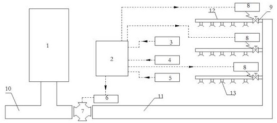
[0019] like figure 1 As shown in the figure, the present invention provides a fire extinguishing device and control method for continuous cooling by multiple injections, including a main conveying pipe 11 and a main controller 2, the main conveying pipe 11 is externally connected with a high-pressure fire extinguishing agent supply source, and the end of the main conveying pipe 11 is connected to There are several groups of spray pipes 12, each group of spray pipes 12 is provided with a number of nozzles 13, and each group of spray pipes 12 is provided with a valve 9, and the valve 9 is provided with an electric valve 9 that can adjust the opening of the valve 9 for execution. The actuator signal of the electric valve 9 is connected with the valve controller 8; the main conveying pipeline 11 is provided with a pressure reducing valve 7, and the pressure reducing valve...


PUM


Abstract

The fire extinguishing device comprises a main conveying pipeline and a main controller, the main conveying pipeline is externally connected with a high-pressure fire extinguishing agent supply source, the tail end of the main conveying pipeline is connected with a plurality of groups of spraying pipes, each group of spraying pipes is provided with a plurality of nozzles, and each group of spraying pipes is provided with a valve. And the signal output end of the main controller is connected with the valve controller and the pressure reducing valve controller. The battery module has the beneficial effects that the after-combustion risk is extremely low, and heat radiation to surrounding batteries is reduced by absorbing heat of the thermal runaway battery, so that heat spreading in the battery module is prevented, and explosion is prevented.

Description

technical field [0001] The invention relates to a fire-extinguishing device and a control method for continuous cooling by multiple injections. Background technique [0002] In recent years, electrochemical energy storage represented by lithium-ion batteries has developed rapidly due to its advantages such as high energy storage density and power density, high efficiency, rapid technological progress, and great development potential. A number of lithium-ion battery energy storage power stations have been established at home and abroad. The high energy density of lithium-ion batteries also leads to potential fire hazards. Once thermal runaway occurs, it is easy to cause thermal diffusion, and the diffusion speed is very fast. In the prior art, in order to extinguish the fire caused by the lithium ion battery in time, one solution is to spray a large dose of cooling extinguishing agent at one time to suppress and extinguish the fire. The pressure of the battery box will incr...

Claims


Application Information

Patent Timeline
Patent Type & Authority Applications(China)
IPC IPC(8): A62C3/16A62C31/02A62C31/28A62C37/40G08B17/10G08B17/06
CPCA62C3/16A62C31/02A62C31/28A62C37/40G08B17/10G08B17/06Y02E60/10
Inventor 顾士友樊琪刘建辉郭子翰吴凡孙伟
Owner 山东雷纳新材料科技有限公司
Learn More