S-shaped fin structure suitable for cooling channel in rear edge of turbine blade
A turbine blade and internal cooling technology, which is applied in the direction of blade support elements, sustainable transportation, climate sustainability, etc., can solve the problems of complex cooling structure, high manufacturing cost, and difficult processing
- Summary
- Abstract
- Description
- Claims
- Application Information
AI Technical Summary
Problems solved by technology
Method used
Image
Examples
Embodiment 1
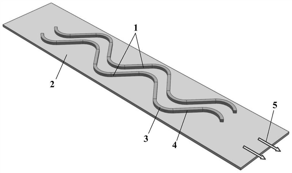
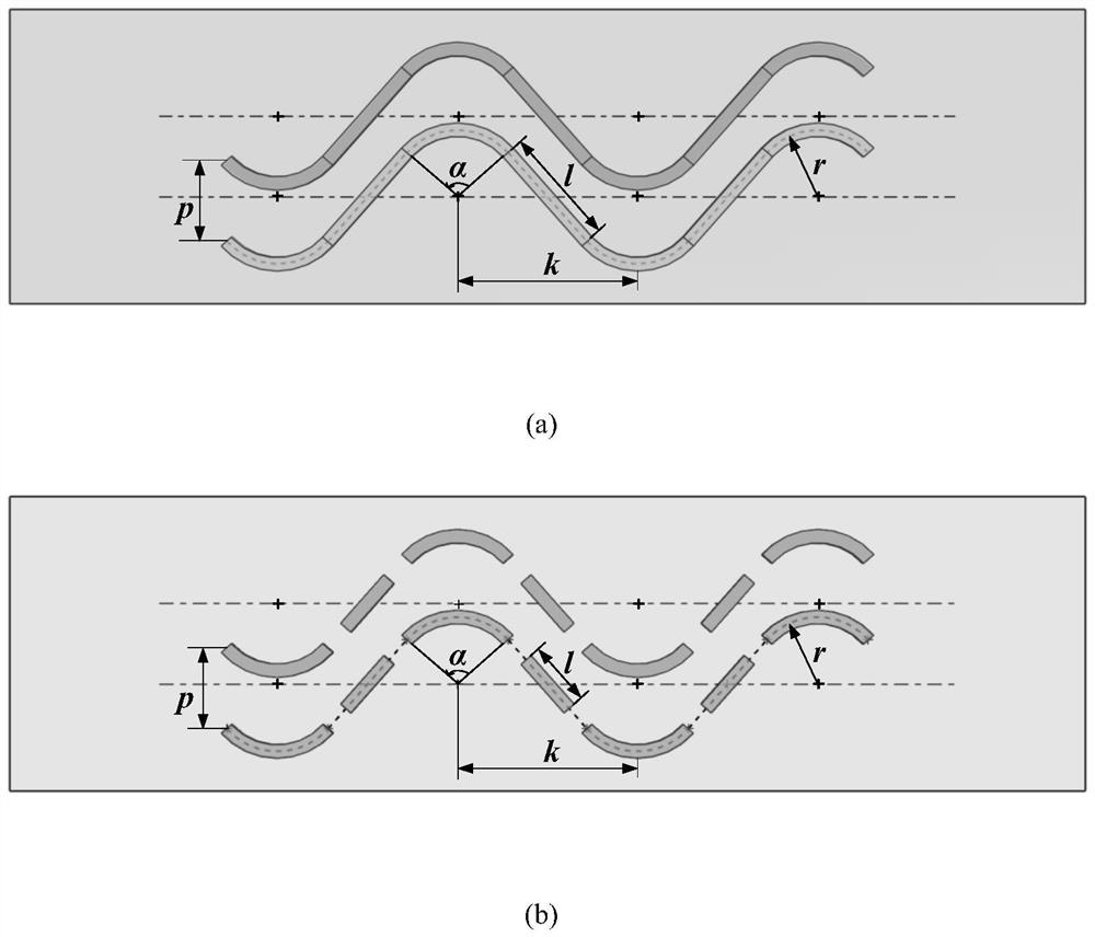
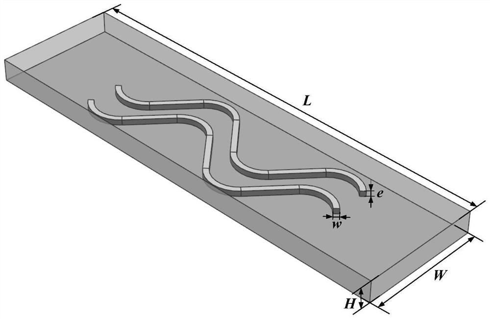
[0026] combine Figure 4 , This embodiment provides an S-shaped fin structure applied to the cooling channel inside the trailing edge of the turbine blade, including the cooling channel and the S-shaped fin. Hydraulic diameter D of cooling channel h = 3mm, the S-shaped fins are composed of 7 arc fins and 6 straight fins arranged alternately in a row. The ratio of the fin height to the hydraulic diameter of the cooling channel is e / D h =0.05 (e=4mm), the width w of the rib is equal to the height e, and the ratio of the radius of the center line of the arc rib to the hydraulic diameter of the channel is r / D h = 0.25 (r=20mm), the ratio of the distance between adjacent arc ribs to the radius of the centerline of the arc rib k / r=2.5 (k=50mm), the radian of the centerline of the arc rib α=106.25°, and the length l=30mm. The S-shaped fins are arranged at equal intervals in the leaf height direction, the ratio of the rib spacing to the radius of the centerline of the arc rib is p / r...
Embodiment 2
[0028] combine Figure 5 , This embodiment provides an S-shaped fin structure applied to the cooling channel inside the trailing edge of the turbine blade, including the cooling channel and the S-shaped fin. Hydraulic diameter D of cooling channel h =3mm, the S-shaped fins are composed of 6 arc fins and 5 straight fins arranged alternately in a row, the ratio of the fin height to the hydraulic diameter of the cooling channel is e / D h =0.05 (e=4mm), the width w of the rib is equal to the height e, and the ratio of the radius of the center line of the arc rib to the hydraulic diameter of the channel is r / D h = 0.25 (r=20mm), the ratio of the distance between adjacent arc ribs to the radius of the centerline of the arc rib k / r=4 (k=80mm), the radian of the centerline of the arc rib α=60°, and the length l=69.28mm. The S-shaped fins are arranged at equal intervals in the leaf height direction, the ratio of the rib spacing to the radius of the centerline of the arc rib is p / r=1.0...
Embodiment 3
[0030] combine Image 6 , This embodiment provides an S-shaped fin structure applied to the cooling channel inside the trailing edge of the turbine blade, including the cooling channel and the S-shaped fin. Hydraulic diameter D of cooling channel h =3mm, the S-shaped fins are composed of 7 arc fins and 6 straight fins alternately arranged intermittently, the ratio of the fin height to the hydraulic diameter of the cooling channel is e / D h =0.05 (e=4mm), the width w of the rib is equal to the height e, and the ratio of the radius of the center line of the arc rib to the hydraulic diameter of the channel is r / D h = 0.25 (r=20mm), the ratio of the distance between adjacent arc ribs to the radius of the centerline of the arc rib k / r=2.5 (k=50mm), the radian of the centerline of the arc rib α=60°, and the length l=18mm. The S-shaped fins are arranged at equal intervals in the leaf height direction, the ratio of the rib spacing to the radius of the centerline of the arc rib is p / r=1...
PUM
 Abstract
Description
Claims
Application Information
 - R&D
- Intellectual Property
- Life Sciences
- Materials
- Tech Scout
- Unparalleled Data Quality
- Higher Quality Content
- 60% Fewer Hallucinations
Browse by: Latest US Patents, China's latest patents, Technical Efficacy Thesaurus, Application Domain, Technology Topic, Popular Technical Reports.
© 2025 PatSnap. All rights reserved.Legal|Privacy policy|Modern Slavery Act Transparency Statement|Sitemap|About US| Contact US: help@patsnap.com


