Internal component of falling film devolatilization tower with bionic structure and devolatilization tower

A technology of devolatilization tower and internal components, applied in the field of devolatilization tower, can solve the problems of uncontrollable falling film time, uneven residence time, low devolatilization efficiency, etc., achieving good commercial significance, enhancing membrane surface renewal, The effect of strengthening the devolatilization effect

Pending Publication Date: 2022-08-09
EAST CHINA UNIV OF SCI & TECH
View PDF1 Cites 0 Cited by
  • Summary
  • Abstract
  • Description
  • Claims
  • Application Information

AI Technical Summary

Problems solved by technology

[0003] At present, a variety of devolatilization equipment has been used in the industrial field. Although the dynamic rotary devolatilization equipment represented by the screw extruder and the disk-ring polycondensation reactor achieves the advantages of enhanced surface renewal and uniform material mixing by means of rotating stirring elements, but The structure is too complicated, and the manufacturing and operating costs are high
The falling film outside the tube or the smooth straight plate type devolatilization tower provides a considerable gas-liquid interface by freely falling film or flowing down the liquid column under the action of gravity and inertial force; when using a single-layer falling film element, due to the polymer solution / melt The viscosity of the body changes continuously with the devolatilization process, which leads to uncontrollable falling time and narrow application range. In addition, during the free falling film process, the material hardly mixes and renews, and it is difficult for the material inside the liquid film to expose the gas-liquid phase interface, resulting in degassing. Low volatilization efficiency, uneven product quality
[0004] In the prior art, multi-layer grid plates with alternating combination of film-forming channels are usually used to realize multi-layer falling film to solve the problems of poor mixing effect, uneven residence time, and poor fluid devolatilization effect. There are still cases where some fluids have not been devolatilized or the devolatilization effect is poor, resulting in uneven fluid quality. To ensure the efficiency and quality of devolatilization, the fluid must be remixed and then devolatilized multiple times. The cost is high and the efficiency is low. Low
[0005] In this regard, Chinese patent CN108434791A discloses an internal component of a high-efficiency devolatilization tower, including a conical top hat, a conical tray, and a support member. The top of the first conical tray is provided with a conical top cap. The bottom of the plate is connected to the top of the second conical tray through an overflow weir, the bottom of the first conical tray is provided with a ring grid plate with a first support, and the bottom of the second conical tray is provided with a ring of second supports. The bottom end of the second support member is connected to the third conical tray, the bottom of the third conical tray is provided with a circle of third support members, the top cross section of the third conical tray is higher than the bottom cross section of the first conical tray, This application has the advantages of small internal flow resistance, no dead zone, good film formation, and fast surface renewal rate, but when it flows on the tray, the static friction force is relatively large, the flow resistance is large, and the fluid is difficult to distribute on the tray. , the film layer is thicker, it is not easy to drop the film, and the devolatilization effect is poor

Method used


Image

  • Internal component of falling film devolatilization tower with bionic structure and devolatilization tower
  • Internal component of falling film devolatilization tower with bionic structure and devolatilization tower
  • Internal component of falling film devolatilization tower with bionic structure and devolatilization tower

Examples


Embodiment 1

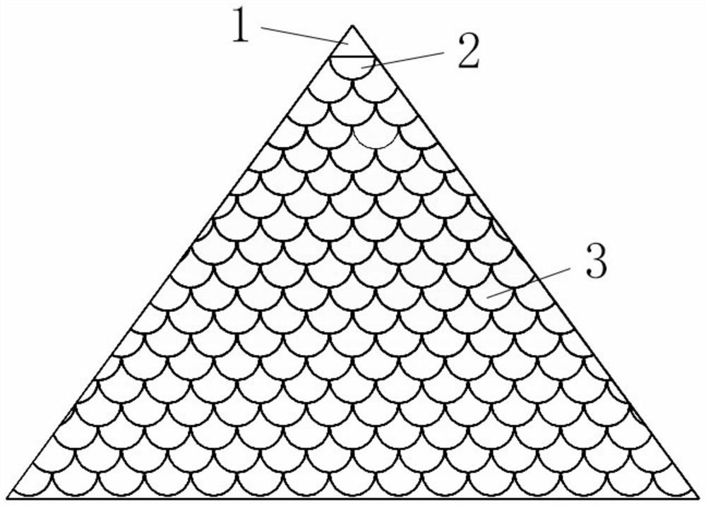
[0045] A bionic structure falling film devolatilization tower internal component, a bionic structure falling film devolatilization tower internal component, including a column plate body 1, a support member 6 located at the bottom of the column plate body, and a falling film member 2 located on the surface of the column plate body. , a plurality of bionic structural elements 3 are arranged in the falling film member, and the support member 6 is used to increase the fluid film forming area.

[0046] In this embodiment, the falling film components are distributed on the surface of the tray body, and are arranged into several layers of falling film components, and the distance between the two adjacent layers of the falling film components is the same.

[0047] Further, the column plate body is a conical column plate, the upper end of the column plate body is a cone angle, and the number of bionic structural elements in the falling film assembly increases sequentially along the flu...

Embodiment 2

[0063] This embodiment is carried out on the basis of the above-mentioned first embodiment, and the same points as the above-mentioned embodiment will not be repeated.

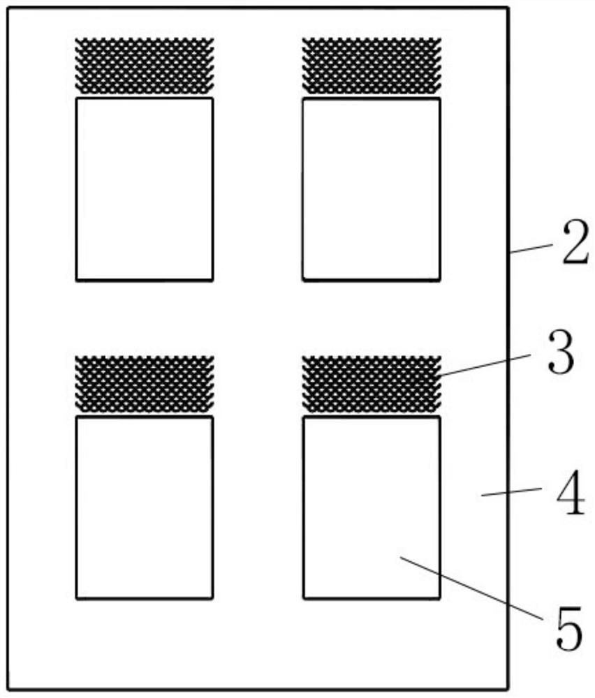
[0064] In this embodiment, the falling-film components are distributed below the column body, the falling-film components include a falling-film plate 4 with a window 5, and the bionic structural element is located in the falling-film plate with a window. place.

[0065] Further, a plurality of the biomimetic structural elements are evenly arranged above the window of the falling film plate, two adjacent rows of biomimetic structural elements are arranged at intervals, and the biomimetic structural elements in the upper row partially cover the biomimetic structural elements in the next row. on structural elements.

[0066] Further, the length of each window is: 10-200mm, more preferably 20-100mm; the height of each window is: 10-200mm, more preferably 20-100mm; the spacing between adjacent windows is 10-100mm...

Embodiment 3

[0068] This embodiment is carried out on the basis of the above-mentioned first or second embodiment, and the same points as the above-mentioned embodiment will not be repeated.

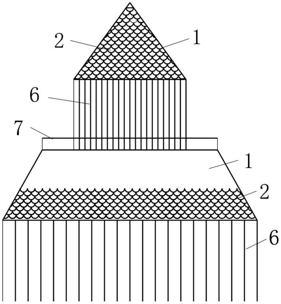
[0069] like image 3 As shown, this embodiment mainly introduces a devolatilization tower, which includes a tower body, a fluid distributor located inside the tower body, and several internal components of the falling film devolatilization tower with bionic structure as described in the first embodiment. , the fluid distributor is located above the internal components of the bionic structure falling film devolatilization tower, and the support is located between the two internal components of the bionic structure falling film devolatilization tower.

[0070] Further, the length of each support is 5-1000mm, more preferably 10-200mm.

[0071] In this embodiment, the shape of the tray bodies of the inner components of the two adjacent biomimetic structure falling film devolatilization towers are differ...


PUM

PropertyMeasurementUnit
diameteraaaaaaaaaa
diameteraaaaaaaaaa
heightaaaaaaaaaa

Abstract

The invention discloses a bionic structure falling film devolatilization tower internal component and a devolatilization tower. The bionic structure falling film devolatilization tower internal component comprises a tower plate body, a supporting piece located at the bottom of the tower plate body and a falling film piece located on the surface of the tower plate body, and a plurality of bionic structure elements are arranged in the falling film piece. The bionic structural element is arranged on the tower plate body, and compared with a traditional conical falling film element, static friction can be converted into sliding friction, so that the flow resistance is reduced, the average flow velocity of a high-viscosity fluid on an umbrella plate is increased, the thickness of a film on a conical plate is reduced, and heat and mass transfer is enhanced; by means of the multilayer embedded and stacked bionic structural elements, fluid near the wall face can move towards the surface of the membrane, and therefore the effects of enhancing membrane surface updating, facilitating VOCs removal and enhancing the devolatilization effect are achieved.

Description

technical field [0001] The invention relates to the technical field of devolatilization towers, in particular to a bionic structure falling film devolatilization tower internal components bionic structure falling film devolatilization tower internal components and a devolatilization tower. Background technique [0002] In the prior art, devolatilization is an important link in chemical production, and its task is to transfer volatile substances from the liquid phase to the gas phase to be discharged from the fluid. The devolatilization effect directly affects the quality and application of the product, and its importance is second only to the polymerization process and process formula. [0003] At present, a variety of devolatilization equipment has been used in the industrial field. Although the dynamic rotary devolatilization equipment represented by screw extruders and disc ring polycondensation reactors achieves the advantages of enhanced surface renewal and uniform mixi...

Claims


Application Information

Patent Timeline
Patent Type & Authority Applications(China)
IPC IPC(8): B01D19/00B01D3/32
CPCB01D19/0021B01D3/32
Inventor 奚桢浩黄剑清朱志华赵玲仇枭逸王雪松赵鸣张林李响
Owner EAST CHINA UNIV OF SCI & TECH
Why Eureka
Try Eureka