Straw carbonization equipment

A technology of straw carbonization and equipment, which is applied in stationary carbonization furnaces, biofuels, coke ovens, etc., can solve the problems of energy waste, low carbonization rate, affecting crop growth, etc. Effect

Active Publication Date: 2022-08-09
南京清发同利科技有限公司
View PDF2 Cites 0 Cited by
  • Summary
  • Abstract
  • Description
  • Claims
  • Application Information

AI Technical Summary

Problems solved by technology

[0002] Carbonization is one of the effective measures for resource utilization of crop straw, which can solve the problems of straw waste, field incineration pollution and greenhouse gas emissions. If the straw is not crushed in place, returning the straw directly to the field will also affect the growth of the crops, and it is not conducive to the suppression of pests and diseases. However, using carbonization to return to the field can avoid these problems
[0003] The straw carbonization equipment on the market is still mainly fixed, but in the prior art, there are still movable in-situ carbonization and field machinery, such as CN110819368A A disclosed harvester-loaded double-wing straw carbonization and returning device in situ can be loaded on a harvester, which includes a pretreatment feeding system, a pyrolysis carbonization system, a circulating heating system and a product collection system, and has a compact structure. It has the advantages of light weight, small size, easy loading and unloading, and high processing efficiency; but it also has disadvantages, mainly because the straw entering the pyrolysis carbonization system contains a large amount of water, and the evaporation of water during cracking will take away a large amount of heat, resulting in waste of energy. Incomplete carbonization of straw, followed by the fact that the straw is in a dispersed state, there is a large amount of oxygen in the carbonization furnace, and the oxidation at high temperature leads to a low carbonization rate.

Method used


Image

  • Straw carbonization equipment
  • Straw carbonization equipment
  • Straw carbonization equipment

Examples


Embodiment Construction

[0020] The technical solutions in the embodiments of the present invention will be clearly and completely described below. Obviously, the described embodiments are only a part of the embodiments of the present invention, rather than all the embodiments. Based on the embodiments of the present invention, all other embodiments obtained by those of ordinary skill in the art without creative efforts shall fall within the protection scope of the present invention.

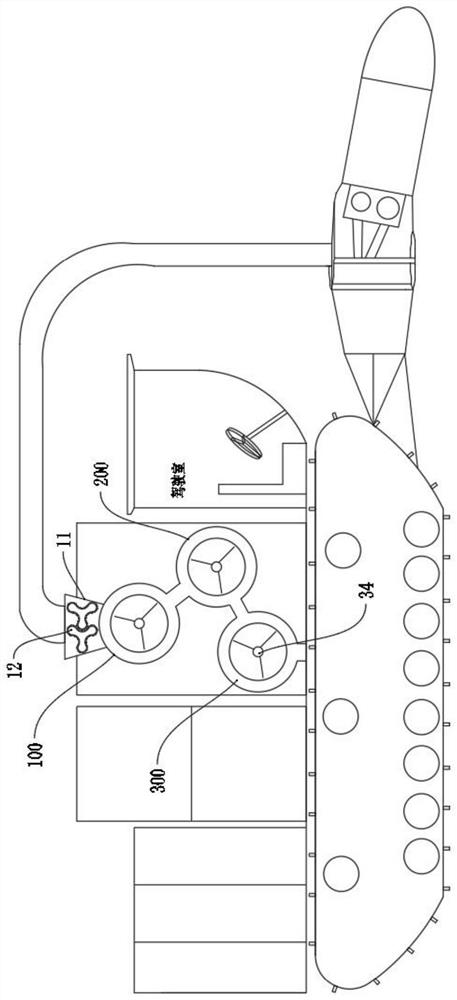
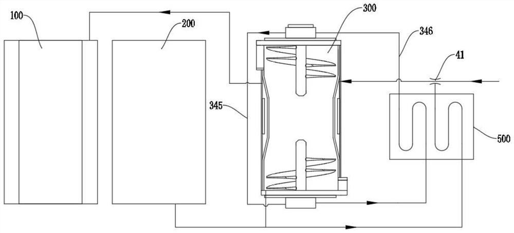
[0021] like Figure 1-5 As shown, a straw carbonization device in this embodiment can be installed on a mobile machine related to agriculture, such as a harvester, etc., and the mobile machine can have a straw picking mechanism, a straw crushing mechanism and a feeding mechanism. Necessary equipment, but as an extended use method, the straw carbonization equipment of the present application can also be used as a separate stationary equipment.

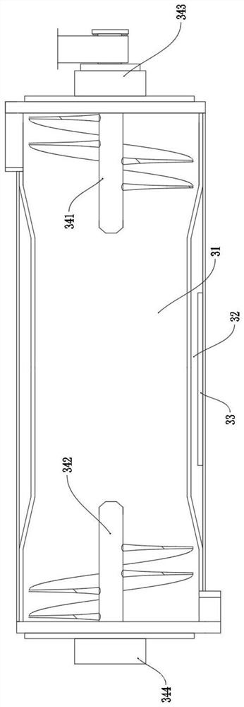
[0022] The straw carbonization equipment includes a casing with a thermal i...


PUM


Abstract

The invention relates to the field of agricultural machinery, in particular to straw carbonization equipment which comprises a machine shell, a dehumidification preheating furnace, a pre-carbonization furnace and a main carbonization furnace are arranged in the machine shell, a feeding port is formed in the top of one end of the dehumidification preheating furnace, and a channel communicated to the pre-carbonization furnace is arranged at the other end of the dehumidification preheating furnace; a channel communicated with the main carbonization furnace is arranged at the other end of the pre-carbonization furnace, and an auger mechanism with the feeding volume larger than the discharging volume is arranged in the main carbonization furnace; the straw is heated and carbonized in a multi-stage heating mode, the straw is compressed, and the carbon yield is increased.

Description

technical field [0001] The invention relates to the field of agricultural machinery, in particular to a straw carbonization device. Background technique [0002] Carbonization is one of the effective measures for the utilization of crop straw resources. It can solve the problems of straw waste, field burning pollution and greenhouse gas emissions. The straw is directly crushed and returned to the field, and the straw is not properly crushed. The direct return of the straw to the field will also affect the growth of crops. In addition, it is not conducive to inhibiting diseases and insect pests, and the use of carbonization to return to the field can avoid these problems. [0003] The straw carbonization equipment on the market is still mainly fixed, but there are still mobile in-situ carbonization and returning machines in the prior art, such as a harvester-loaded double-wing type straw in-situ carbonization and returning machine disclosed in CN110819368A. The field device,...

Claims


Application Information

Patent Timeline
Patent Type & Authority Applications(China)
IPC IPC(8): C10B53/02C10B57/10C10B1/02C10B47/06C10B47/44
CPCC10B53/02C10B57/10C10B1/02C10B47/44C10B47/06Y02E50/10
Inventor 张清发
Owner 南京清发同利科技有限公司
Why Eureka
Try Eureka