Liquid hydrogen conveying pipeline

A technology for transporting pipelines and liquid hydrogen, which is applied in pipeline protection, pipeline heating/cooling, and pipeline protection through thermal insulation, etc. It can solve problems such as aggravating hydrogen energy loss, achieve uniform force, reduce thermal energy loss, and reduce contact area. Effect

Pending Publication Date: 2022-08-09
CHENGDU CRAER CRYOGENIC EQUIP
View PDF0 Cites 0 Cited by
  • Summary
  • Abstract
  • Description
  • Claims
  • Application Information

AI Technical Summary

Problems solved by technology

[0003] However, liquid hydrogen has high requirements for storage and transportation, and needs to be kept at a low temperature. Generally, high-pressure storage or normal-pressure storage is selected for storage, but there will be considerable losses. Liquid hydrogen is a liquid fuel obtained by processing hydrogen at high pressure and low temperature , in the process of transportation, it is necessary to ensure the stress and heat exchange of the pipeline. Due to the inevitable heat exchange in the transportation process, the loss of hydrogen energy is aggravated in the transportation process. The design of the pipeline in the transportation process It is closely related to the transportation capacity and loss of liquid hydrogen. How to ensure the stability and low loss of liquid hydrogen transportation pipelines is an urgent problem to be solved at present.

Method used


Image

  • Liquid hydrogen conveying pipeline
  • Liquid hydrogen conveying pipeline
  • Liquid hydrogen conveying pipeline

Examples


Embodiment 1

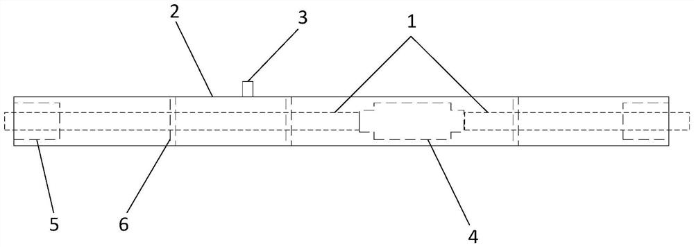
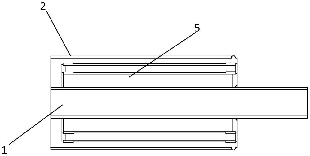
[0036] Embodiment 1 of the present invention provides a liquid hydrogen transport pipeline, such as figure 1 As shown in the figure, it includes at least one conveying pipeline. In this embodiment, the conveying pipeline adopts a double-layer structure, including an inner pipe 1 and an outer pipe 2. The inner pipe 1 is arranged in the outer pipe 2 and is coaxial with the outer pipe 2. An interlayer space is formed between the inner pipe 1 and the outer pipe 2, and the outer pipe 2 is provided with a vacuum suction port 3 that penetrates the interior of the outer pipe 2, and the air in the interlayer space is evacuated through the vacuum suction port 3, The liquid hydrogen medium is transported in the inner tube 1, the interlayer space is in a vacuum to reduce heat energy transfer, and the outer tube 2 is used to separate the inner space from the atmospheric environment.

[0037] Between the inner pipe 1 and the outer pipe 2, a plurality of thermal insulation support components...

Embodiment 2

[0049] Embodiment 2 of the present invention provides a liquid hydrogen transportation pipeline, and the overall structure of the transportation pipeline is based on the above-mentioned Embodiment 1, and details are not repeated here.

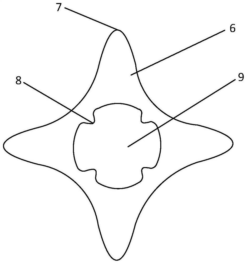
[0050] like figure 2 As shown, in this embodiment, the heat insulating support assembly 6 is provided with a through hole 9 in the middle, through which the through hole 9 is sleeved on the outside of the inner tube 1, and the heat insulating support assembly 6 has a symmetrical structure as a whole. The through hole 9 is sleeved on the outer side of the inner pipe 1 to realize the support, so that the force is uniform everywhere in the pipe, and the uneven weight distribution of the thermal insulation support assembly 6 itself is avoided to affect the force in the conveying pipeline;

[0051] The adiabatic support assembly includes a number of symmetrical fulcrums 7, which are supported between the inner tube 1 and the outer tube 2 through th...

Embodiment 3

[0056] Embodiment 3 of the present invention provides a liquid hydrogen transportation pipeline, and the overall structure of the transportation pipeline is based on the above-mentioned Embodiment 1 or 2, and details are not repeated here.

[0057] In this embodiment, there is also a fixing member on the thermal insulation support assembly 6, and the fixing member includes a mounting portion 10 and a fixing portion 11, and the mounting portion 10 is provided in the concave structure of the connecting portion between the fulcrums When fixing, the fixing portion 11 is on either side of the two sides of the heat insulating support assembly 6 , and the fixing portion 11 and the inner tube 1 are clamped to the outside of the inner tube 1 in the same direction.

[0058] The fixing portion 11 is adapted to the shape and structure of the outer side of the inner tube 1, so as to better fit the outer side of the inner tube.

[0059] Specifically, in this embodiment, the fixing portion 1...


PUM


Abstract

The invention discloses a liquid hydrogen conveying pipeline which comprises at least one section of conveying pipeline, the conveying pipeline comprises an inner pipe and an outer pipe, the inner pipe is arranged in the outer pipe and is coaxial with the outer pipe, a vacuum interlayer space is formed between the inner pipe and the outer pipe, a plurality of heat insulation supporting assemblies are further arranged between the inner pipe and the outer pipe, and a heat bridge assembly is arranged at the end of each section of conveying pipeline. The heat bridge assembly is arranged between the inner pipes and the outer pipe, expansion joints are arranged between the inner pipes in a sleeved mode, and a vacuum pumping opening penetrating through the interior of the outer pipe is formed in the outer pipe. A double-layer structure is adopted, a liquid hydrogen medium is conveyed through the inner pipe, vacuum is formed between the inner pipe and the outer pipe, the heat insulation supporting assembly is used for supporting, pipeline rigidity is guaranteed, stable conveying of liquid hydrogen is achieved, heat energy transfer is reduced, and loss in the liquid hydrogen conveying process is reduced.

Description

technical field [0001] The invention relates to the technical field of liquid hydrogen transmission pipelines, in particular to a liquid hydrogen transmission pipeline. Background technique [0002] Under normal temperature and pressure, hydrogen is a colorless, transparent, odorless, tasteless, insoluble in water, and highly flammable gas. Hydrogen is a gas with the smallest density. It is very easy to burn and explode under normal temperature and pressure. Therefore, in the development of hydrogen energy, the storage and transportation of hydrogen is particularly important. It is liquefied by high pressure and cooling to obtain liquid hydrogen. Liquid hydrogen is currently an important high-energy low-temperature liquid fuel with high energy conversion rate and good fuel economy. Therefore, with the intensification of energy and environmental problems, liquid hydrogen is used. Hydrogen as a clean energy has a wide range of applications in various fields. [0003] However...

Claims


Application Information

Patent Timeline
IPC IPC(8): F16L9/18F16L59/065F16L51/00F16L53/30F16L57/02
CPCF16L9/18F16L59/065F16L51/00F16L53/30F16L57/02Y02P90/45
Inventor 罗敏邹波雒川彭万清
Owner CHENGDU CRAER CRYOGENIC EQUIP
Why Eureka
Try Eureka