
Sintering kiln

A sintering kiln and sintering furnace technology, applied in the field of sintering furnaces, can solve the problems of high labor intensity, high pressure in the furnace, air pollution, etc., and achieve the effects of increasing work efficiency, uniform heating, and ensuring quality

Pending Publication Date: 2022-08-09
严照旭
View PDF0 Cites 1 Cited by
  • Summary
  • Abstract
  • Description
  • Claims
  • Application Information

AI Technical Summary

Problems solved by technology

[0003] However, the following problems will occur when the existing sintering furnace is in use: 1. Before the sintering furnace is used, the materials need to be sent to the sintering furnace. Low efficiency; 2. The sintering furnace will emit a large amount of flue gas during the combustion process, and the natural emission will cause air pollution. The existing sintering furnace usually installs a filter mechanism in the furnace to filter the exhaust gas, but the traditional sintering furnace filter mechanism will If the gas overflows too slowly, the gas pressure in the furnace will be too high, which will cause damage to the equipment in the furnace, and the furnace cannot be heated; 3. The gas circulation in the furnace is not good when the existing sintering furnace is sintered, which will cause the material The uneven heating will affect the quality of sintering, so we propose a sintering kiln

Method used


Image

  • Sintering kiln
  • Sintering kiln
  • Sintering kiln

Examples


Embodiment Construction

[0024] The embodiments of the present invention are described in detail below with reference to the accompanying drawings, but the present invention can be implemented in many different ways as defined and covered by the claims.

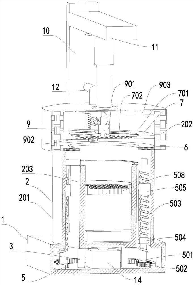
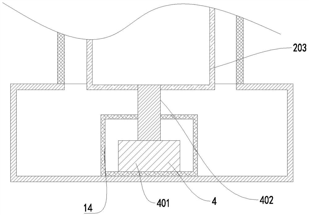
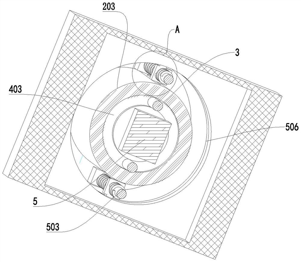
[0025] see Figure 1-4 , a sintering furnace, including a bottom shell 1 and a sintering furnace body 2, the sintering furnace body 2 includes a sintering furnace outer cylinder 201, a cover 202 and a sintering furnace inner tank 203, and the sintering furnace outer cylinder 201 is fixedly connected to the top of the bottom shell 1 , the cover 202 is threadedly connected with the top of the outer cylinder 201 of the sintering furnace, the interior of the bottom shell 1 is hollow design, the inner surface of the bottom end of the bottom shell 1 is fixedly connected with two support blocks 3, the bottom shell 1 is provided with a rotating feeding mechanism 5, and the bottom Inside the casing 1 is a driving mechanism 4 that cooperates with the rotating ...


PUM


Abstract

The invention relates to the technical field of sintering furnaces, in particular to a sintering kiln. Comprising a bottom shell and a sintering furnace body, the sintering furnace body comprises a sintering furnace outer barrel, a machine cover and a sintering furnace inner container, the sintering furnace outer barrel is fixedly connected to the top end of the bottom shell, threaded surfaces are arranged inside the bottom end of the machine cover and outside the top end of the sintering furnace outer barrel, and the machine cover is in threaded connection with the top end of the sintering furnace outer barrel; through the designed filtering assembly, the reciprocating mechanism matched with the filtering assembly to work and the material spreading mechanism, combustion waste gas in the furnace can rapidly pass through filtered gas materials, and the problem that the gas pressure in the furnace is too large due to the fact that the waste gas overflows too slowly is solved; the sintering furnace is flexible, an operator can place materials to be sintered conveniently, and the working efficiency is improved.

Description

technical field [0001] The invention relates to the technical field of sintering furnaces, in particular to a sintering furnace. Background technique [0002] The sintering kiln is a device made of refractory materials for sintering products. It is an essential facility in ceramic hot pressure injection molding. By adding ceramic materials into the furnace, the electric heat source sinters the materials to obtain sintered products. . [0003] However, the existing sintering furnaces have the following problems when they are used: 1. The sintering furnace needs to send the materials to the sintering furnace before use. Low efficiency; 2. The sintering furnace will emit a large amount of flue gas during the combustion process, and the natural emission will cause air pollution. The existing sintering furnace usually installs a filter mechanism in the furnace to filter the exhaust gas, but the traditional sintering furnace filter mechanism will There is a problem that the gas ...

Claims


Application Information

Patent Timeline
IPC IPC(8): F27B17/00F27D3/12F27D17/00
CPCF27B17/005F27D3/12F27D17/008F27D2003/0086F27M2001/1504F27M2003/04Y02P10/143
Inventor 严照旭
Owner 严照旭
Learn More