Inshore underwater slope bedrock blasting excavation construction method and blasting charging structure

A construction method and slope technology, applied in blasting, drilling equipment and methods, earthwork drilling and mining, etc., can solve problems such as different blasting mechanism and construction technical requirements, complex operating environment, vibration and large unit consumption

Pending Publication Date: 2022-08-09
广西桂物爆破工程有限公司 +1
View PDF7 Cites 2 Cited by
  • Summary
  • Abstract
  • Description
  • Claims
  • Application Information

AI Technical Summary

Problems solved by technology

However, the blasting mechanism and construction technical requirements of underwater blasting and land blasting are significantly different due to the difference in blasting medium, and the construction technology process is significantly different
Usually, the underwater drilling and blasting operation environment is complicated, that is, it is affected by sea waves, tides, and swells, resulting in frequent changes in water level, current, sediment and other factors. The multi-field coupling effect of pressure and water resistance makes drilling platform (ship) fixing, drilling positioning, drilling accuracy, explosive filling and plugging quality control more difficult than land construction, and construction quality is difficult to guarantee
[0003] In related technologies, rock-based port and waterway projects often use the drilling and blasting method for construction, that is, the method of excavating rocks by drilling, charging, and blasting. The vibration and unit consumption of this construction method are relatively large, and the cost of blasting also higher

Method used


Image

  • Inshore underwater slope bedrock blasting excavation construction method and blasting charging structure
  • Inshore underwater slope bedrock blasting excavation construction method and blasting charging structure
  • Inshore underwater slope bedrock blasting excavation construction method and blasting charging structure

Examples


Embodiment Construction

[0040] The technical solutions in the embodiments of the present invention will be clearly and completely described below with reference to the accompanying drawings in the embodiments of the present invention. Obviously, the described embodiments are only a part of the embodiments of the present invention, not all of the embodiments. Based on the embodiments of the present invention, all other embodiments obtained by those of ordinary skill in the art without creative efforts shall fall within the protection scope of the present invention.

[0041] It should be noted that all directional indications (such as up, down, left, right, front, back, etc.) in the embodiments of the present invention are only used to explain the relationship between various components under a certain posture (as shown in the accompanying drawings). The relative positional relationship, the movement situation, etc., if the specific posture changes, the directional indication also changes accordingly. ...


PUM


Abstract

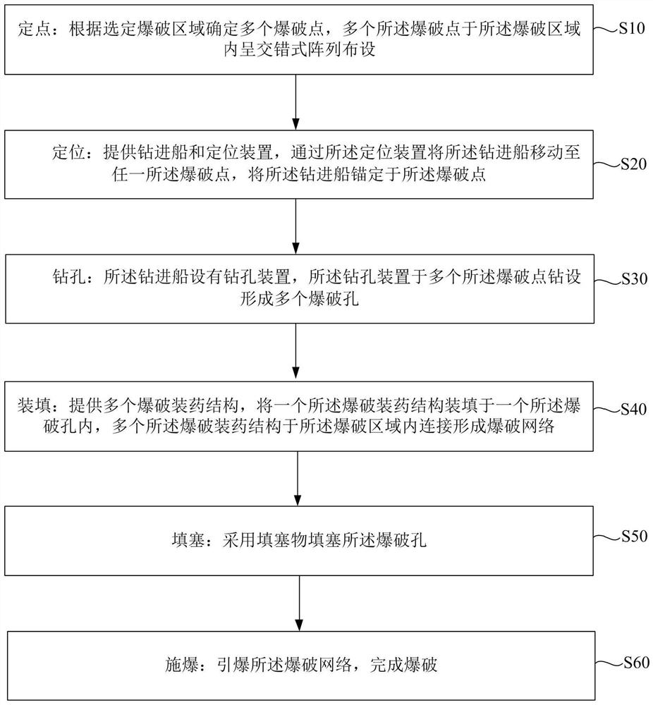
The invention discloses an offshore underwater slope bed rock blasting excavation construction method and a blasting charging structure applied to the method, and the offshore underwater slope bed rock blasting excavation construction method sequentially comprises the steps of point fixing, positioning, drilling, filling and blasting. Specifically, a plurality of blasting points are determined according to a selected blasting area, the blasting points are distributed in the blasting area in a staggered array mode, a drilling ship is moved to the blasting points through a positioning device, the drilling ship is anchored to the blasting points, and a plurality of blasting holes are formed in the blasting points through drilling accurately determined by a drilling device. And the multiple blasting holes are sequentially filled with the multiple blasting charging structures, a blasting network is completed according to design connection, the blasting network is set to be in a millisecond delay blasting mode, the blasting network is excited and detonated, and blasting is completed. According to the offshore underwater slope bedrock blasting excavation construction method, the blasting effect is good, the unit consumption of blasting explosives is low, and the blasting construction cost is low.

Description

technical field [0001] The invention relates to the technical field of offshore underwater blasting, in particular to a construction method and a blasting charge structure for blasting and excavating the bedrock of a near-shore underwater slope. Background technique [0002] At present, the construction of near-coastal and port projects is developing rapidly, involving the reconstruction of port wharves and the excavation of submerged bedrocks, tunnels and shorelines of new port projects. However, the blasting mechanism and construction technology requirements of underwater blasting and land blasting are significantly different due to the difference of blasting medium, and the construction technology and process are significantly different. Usually, the underwater drilling and blasting operation environment is complex, that is, due to the influence of wind and waves, tides and swells on the sea surface, causing frequent changes in water level, current, sediment and other fac...

Claims


Application Information

Patent Timeline
Patent Type & Authority Applications(China)
IPC IPC(8): F42D1/10F42D3/04E21B7/00E21B7/124
CPCF42D1/10F42D3/04E21B7/007E21B7/1245
Inventor 张志雄廖承立周祥云吴宁陈朝章黄海东叶雪云周毅刚石倡溶
Owner 广西桂物爆破工程有限公司
Why Eureka
Try Eureka