Magnetic suspension ring rotor structure for aviation shaftless rim electric propulsion

A ring rotor and electric propulsion technology, applied in the field of aviation electric propulsion, can solve the problems of reducing the axial size and mass of the ring rotor, low tensile strength of the rotor yoke material, low rotor speed, etc. Ring rotor structure, weight reduction effect

Pending Publication Date: 2022-08-09
BEIHANG UNIV +1
View PDF0 Cites 0 Cited by
  • Summary
  • Abstract
  • Description
  • Claims
  • Application Information

AI Technical Summary

Problems solved by technology

[0007] In order to solve the problems of low rotor speed, overweight rotor and low tensile strength of rotor yoke material in high-speed aviation rim electric propulsion devices, the present invention proposes a magnetic levitation ring rotor structure for aviation shaftless rim electric propulsion. One side of the ring rotor Thrust disc and two radial yokes are designed to efficiently couple the ring rotor with the magnetic suspension support system; the control magnetic flux is generated by the support control winding, and the amorphous alloy material is used as the rotor yoke to realize the magnetic suspension between the ring rotor and the radial magnetic bearing. Road coupling, to achieve magnetic suspension support, so that the rotor has low friction and noise at high speeds, reduces the axial size and quality of the ring rotor, and enables the ring rotor to work stably under high speed conditions

Method used


Image

  • Magnetic suspension ring rotor structure for aviation shaftless rim electric propulsion
  • Magnetic suspension ring rotor structure for aviation shaftless rim electric propulsion
  • Magnetic suspension ring rotor structure for aviation shaftless rim electric propulsion

Examples


Embodiment Construction

[0023] In order to make the objectives, technical solutions and advantages of the present invention clearer, the present invention will be further described in detail below with reference to the accompanying drawings and embodiments. It should be understood that the specific embodiments described herein are only used to explain the present invention, but not to limit the present invention. In addition, the technical features involved in the various embodiments of the present invention described below can be combined with each other as long as they do not conflict with each other.

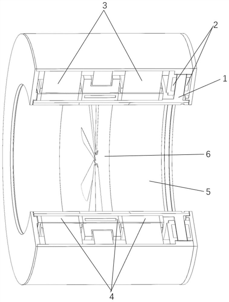
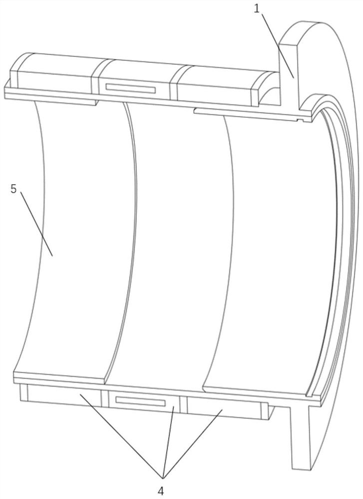
[0024] figure 1 It is a schematic diagram of the magnetic suspension ring rotor of the aviation shaftless rim electric propulsion provided by the embodiment, which can be divided into a ring rotor (1), an axial magnetic bearing (2), a radial magnetic bearing (3), and a rotor yoke (4). ), locking ring structure (5), fan assembly (6). A magnetic suspension support is formed between the radial magnet...


PUM


Abstract

The invention belongs to the technical field of aviation electric propulsion, and relates to a magnetic suspension ring rotor structure for aviation shaftless rim electric propulsion, which comprises a ring rotor (1), an axial magnetic bearing (2), a radial magnetic bearing (3), a rotor magnet yoke (4), a locking ring structure (5) and a fan assembly (6), magnetic suspension supporting is formed between the radial magnetic bearing (3) and the rotor magnet yoke (4), and the requirements for loss reduction and noise reduction of high-speed rotor rotation of aviation shaftless rim electric propulsion are met. The axial length of the ring rotor (1) is short, a thrust disc is small, and the critical rotating speed of the rotor under the action of the magnetic suspension bearing can be improved; the main body of the ring rotor (1) is made of a graphene composite reinforced aluminum-based material, so that the structural weight of the ring rotor (1) is effectively reduced, and the design difficulty of the radial magnetic bearing (3) is reduced; the rotor magnet yoke (4) is made of a high-strength amorphous alloy material, so that the use of a rotor protection sleeve is avoided, and the target of further weight reduction is achieved; the ring rotor (1) and the fan assembly (6) are integrally designed, and the fan assembly (6) is disassembled and assembled through the locking ring structure (5). According to the structure, the quality and speed characteristics of the shaftless rim electric propulsion high-speed rotor are improved, and the reliability of an aviation shaftless rim electric propulsion system is improved.

Description

[0001] Technical field [0002] The invention belongs to the technical field of aviation electric propulsion, and more particularly relates to a magnetic suspension ring rotor structure for aviation shaftless wheel rim electric propulsion. Background technique [0003] Facing the development goals of high power and high power density of aircraft, the size, strength and mass requirements of the propulsion system for the propulsion system have also increased. The aviation shaftless rim thruster cancels the complex transmission shafting and closed system in the traditional thruster, improves the flexibility of the thruster layout, and the integration and integration of the propulsion device can effectively reduce the structural mass. [0004] For wheel rim thrusters, conventional rolling bearing supports are subject to great wear and noise in the higher rotational speed range, limiting the speed performance of the rim thrusters. The non-contact magnetic bearing has the character...

Claims


Application Information

Patent Timeline
Patent Type & Authority Applications(China)
IPC IPC(8): H02K7/09H02K1/22H02K1/27H02K1/02H02K7/14H02N15/00B64D27/24
CPCH02K7/09H02K1/22H02K1/27H02K1/02H02K7/14H02N15/00B64D27/24Y02T50/60
Inventor 何鹏锦杨文将姚轩宇蒋承志白明亮王少鹏张云帆
Owner BEIHANG UNIV
Why Eureka
Try Eureka