3D-imaging system

A technology of 3D imaging and 3D information, applied in image data processing, image data processing, optics, etc., can solve problems such as inaccurate systems, expensive equipment, and high relative noise levels, and achieve increased depth data, low production costs, and Enhanced Calibration Effects

Inactive Publication Date: 2004-07-28
北京三维世界科技有限公司
View PDF20 Cites 5 Cited by
  • Summary
  • Abstract
  • Description
  • Claims
  • Application Information

AI Technical Summary

Problems solved by technology

These combinations can improve the resolution of lateral space, but the relative noise level is too high, generally greater than 5%
[0013] The prior art systems described above are often inaccurate, or require expensive equipment, or require multiple exposures to achieve satisfactory accuracy

Method used


Image

  • 3D-imaging system
  • 3D-imaging system
  • 3D-imaging system

Examples


Embodiment Construction

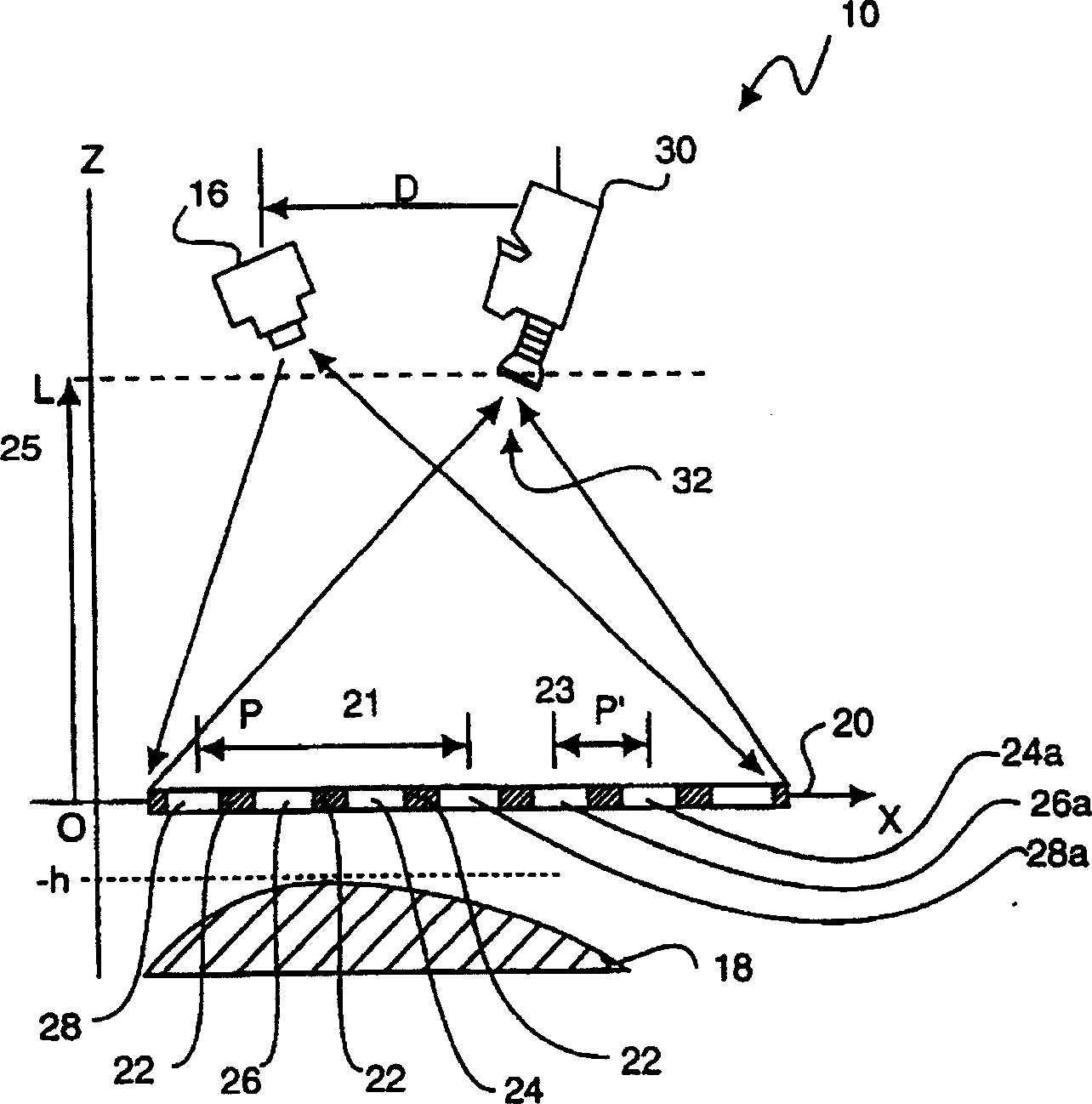
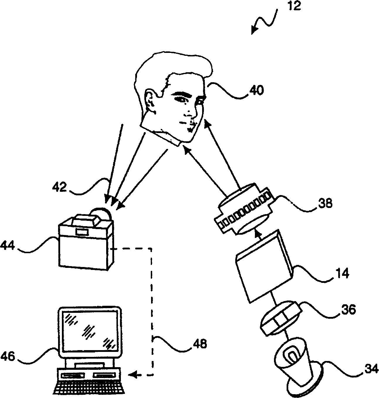
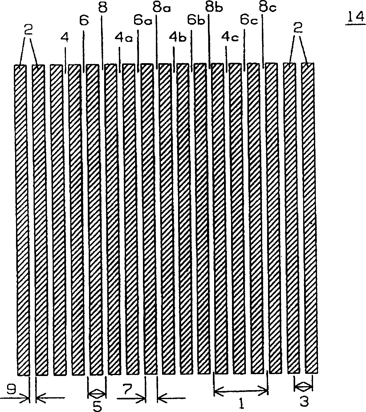
[0041] figure 1 A three-dimensional imaging system is shown, generally indicated at 10, figure 2 An improved three-dimensional imaging system is shown in more detail, generally indicated at 12, image 3 A grating is shown, indicated generally at 14 .

[0042] figure 1 The illustrated three-dimensional imaging system shows a structured light source 16 projecting a structured light pattern (structured illumination) onto an object 18. The light pattern may be or differently color-coded, or any known pattern, easily visualized on the image. Just identify it. A simple yet preferred pattern is that of parallel light bars.

[0043] Light pattern 20 shows a light pattern from structured light source 16 through plane O-X (perpendicular to the plane of the paper) to object 18 . In effect, the light pattern 20 is reflected according to the surface contour of the object 18, and the camera 30 obtains an image of this reflected light, as shown at 32. Object 18 is just a cross section...


PUM


Abstract

A method and apparatus for the imaging of three-dimensional objects is described that includes a structured light source projecting a focused image onto an object by passing either continuous or flashes of collimated source light through an optical grating and proejction lens. Apertures in the grating, optionally transmitting a plurality of distinct colors, impose a known pattern on the projected light, separated by opaque areas which reduce color crosstalk to enhance accuracy. A camera responsive to the projected image captures an image of the projected light reflected from an object. Through short-duration image capture, particularly using a short-duration structured light flash synchronized to a camera using a fast shutter speed, high accuracy static 3D images and measurements of moving or living objects, including humans, can be obtained. The data of the captured image is analyzed to establish and refine the apparent location of points of the reflected pattern.

Description

[0001] related application [0002] This application is a continuation-in-part of US Patent Application Serial No. 09 / 080,135, filed May 15, 1998, and incorporates the subject matter of that US application. technical field [0003] The present invention relates to methods and devices for imaging and measuring three-dimensional surface contours. More specifically, it relates to remote profiling of objects based on a two-dimensional image of the object that reflects structured illumination. Background technique [0004] Three-dimensional (hereinafter referred to as 3D or 3-D) imaging and measurement systems are known, generally in order to obtain the three-dimensional shape of an object, ideally its three-dimensional shape in its actual size. Such imaging and measurement systems are basically divided into two categories: 1) surface contact systems; 2) optical systems. The optical system is further divided into different systems such as laser triangulation, structured illumin...

Claims


Application Information

Patent Timeline
IPC IPC(8): G01B11/00G01B11/25G06T1/00
CPCG01B11/2509
Inventor 陆泰玮张建忠
Owner 北京三维世界科技有限公司
Why Eureka
Try Eureka