A combustion burner of fine coal powder, and a combustion apparatus and method of fine coal powder
A combustion method and burner technology, applied in the direction of combustion method, combustion equipment, burner for burning powder fuel, etc., can solve problems such as improvement
- Summary
- Abstract
- Description
- Claims
- Application Information
AI Technical Summary
Problems solved by technology
Method used
Image
Examples
Embodiment 1
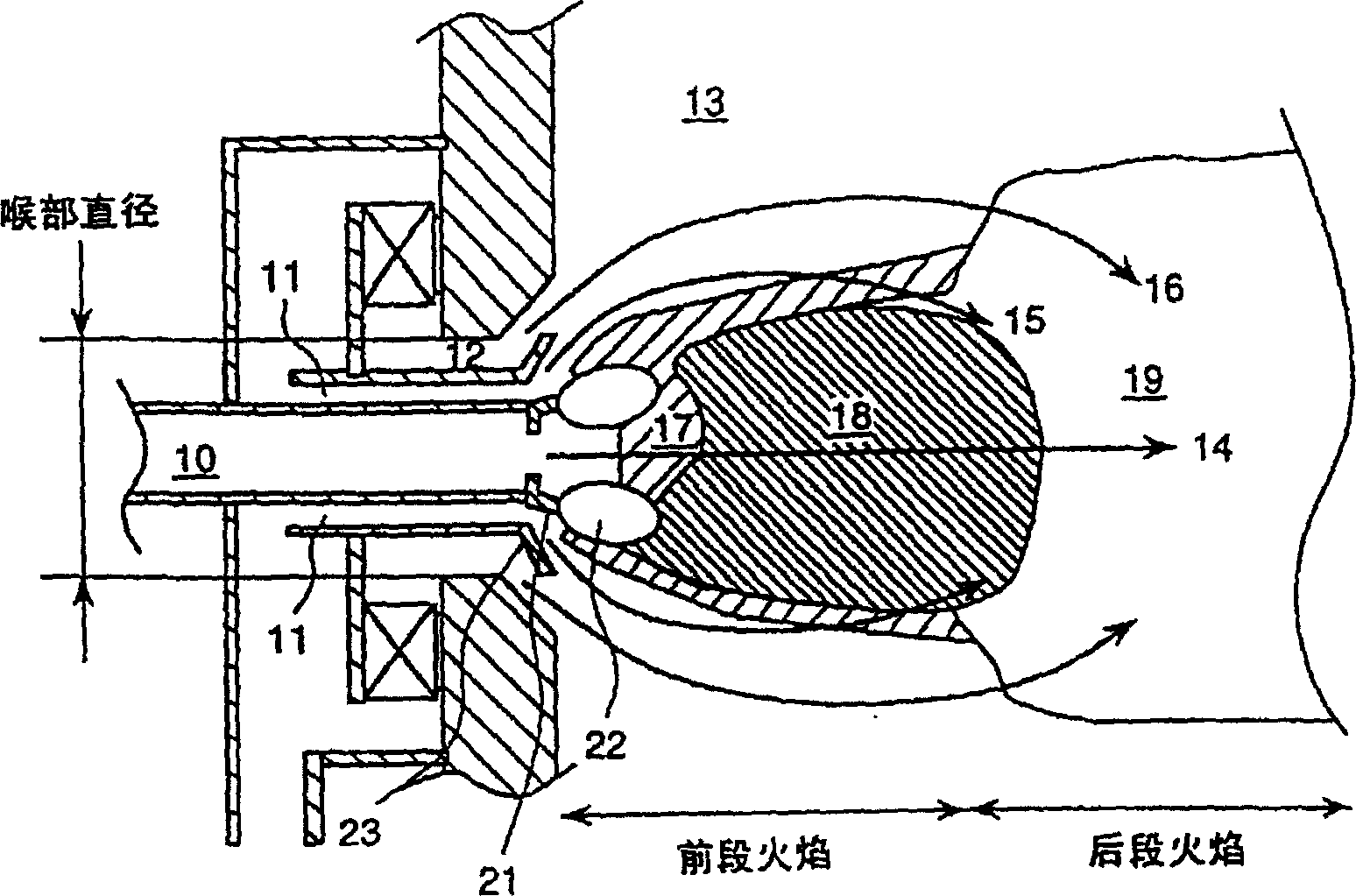
[0038] Below, see Figure 1-Figure 4 The first embodiment of the present invention will be explained.
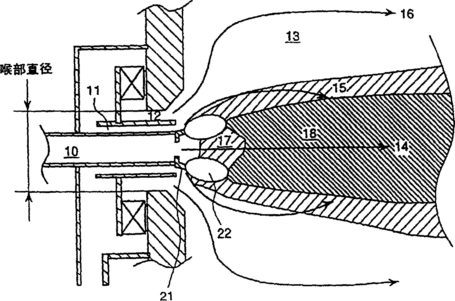
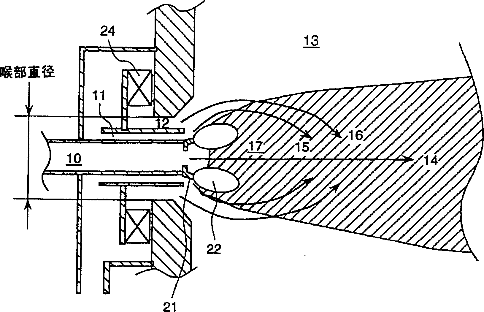
[0039] figure 1 is a schematic diagram of the pulverized coal burner of the present invention, Figure 2-Figure 4 is for with figure 1 The shown pulverized coal burner is shown in comparison with a schematic diagram of a burner in the prior art. Table 1 according to Figure 1-Figure 4 The pulverized coal burner shown lists the NOx concentration and the unburned component content in the embers at the exit of the combustion plant.
[0040] according to Figure 1-Figure 4 In the shown pulverized coal burner, reference numeral 10 denotes a pulverized coal nozzle for conveying pulverized coal by air flow, and a delivery pipe (not shown in the figure) is connected upstream of the nozzle. Two combustion air nozzles are arranged concentrically. Reference numerals 11 and 12 represent the secondary air nozzle and the tertiary air nozzle respectively. Reference numeral 13 denot...
Embodiment 2
[0064] Figure 9 A schematic diagram of a pulverized coal burner showing a second embodiment of the invention. according to Figure 9 , the tuyere is divided into two nozzles such as the secondary tuyere and the tertiary tuyere. A flame stabilization ring 21 is provided on the front end of the pulverized coal nozzle. Figure 9 The present embodiment shown with figure 1 The embodiment shown differs in that it has a spindle 31 in the pulverized coal nozzle.
[0065]Since the spindle body 31 is provided in the pulverized coal nozzle, the velocity of the pulverized coal flow passing through the periphery of the spindle body is increased. After passing the spindle in the nozzle, the air velocity decreases due to the enlarged flow cross-section. However, the pulverized coal particles are ejected at a faster flow rate than air because the pulverized coal particles have a heavier mass than air. Therefore, compared with carrier air, the radial scattering of pulverized coal after ...
Embodiment 3
[0067] Figure 10 is a schematic diagram showing a pulverized coal burner according to a third embodiment of the present invention. according to Figure 10 , Reference numeral 10 represents a pulverized coal nozzle for conveying pulverized coal by air flow, and a conveying pipeline (not shown in the figure) is connected with it upstream of the nozzle. Concentrically set two air nozzles for injecting air for combustion. Reference numerals 11 and 12 represent the secondary air nozzle and the tertiary air nozzle respectively. Reference numeral 13 denotes a furnace space for burning pulverized coal and air from a burner, and 14 denotes a flow of pulverized coal from a pulverized coal nozzle. Reference numerals 15 and 16 represent airflows from the secondary air nozzle and the tertiary air nozzle respectively.
[0068] According to this embodiment, the inner circumference of the outlet of the tertiary air nozzle 12 has a slanted sleeve, and the tertiary air is sprayed away from...
PUM
| Property | Measurement | Unit |
|---|---|---|
| Diameter | aaaaa | aaaaa |
Abstract
Description
Claims
Application Information
 - R&D Engineer
- R&D Manager
- IP Professional
- Industry Leading Data Capabilities
- Powerful AI technology
- Patent DNA Extraction
Browse by: Latest US Patents, China's latest patents, Technical Efficacy Thesaurus, Application Domain, Technology Topic.
© 2024 PatSnap. All rights reserved.Legal|Privacy policy|Modern Slavery Act Transparency Statement|Sitemap


