
External pressing hollow fibre membrane separator and use method thereof

An external pressure hollow fiber and membrane separation technology, applied in semi-permeable membrane separation, chemical instruments and methods, membrane technology, etc., can solve problems such as unscientific water system design, unreasonable water flow design route, and a large amount of raw liquid.

Inactive Publication Date: 2005-08-17
TIANJIN MOTIMO MEMBRANE TECH
View PDF1 Cites 2 Cited by
  • Summary
  • Abstract
  • Description
  • Claims
  • Application Information

AI Technical Summary

Problems solved by technology

But it has such a shortcoming: that is, the "invention method adopts the backwash liquid and air to enter from the nozzle at the lower end of the membrane module, and the water vapor discharged from the top of the membrane module together by the washing liquid and air Cleaning method" (lines 3-5 on page 5 of the application manual), and "after washing, the dirt and air can be discharged through the valve 15 to complete the task of double washing inside and outside
For the design of the water system, due to the bottom-up water flow design route of injecting the backwash liquid and raw liquid from the lower port or the lower side port of the membrane module, and discharging the washed liquid or polluted water from the upper port or the upper side port, Therefore, it is unreasonable to design the water flow route of the backwash liquid or the polluted water with a higher concentration and larger specific gravity from the backwash liquid and the original liquid with a lower concentration and lighter specific gravity, and therefore it is necessary to drain the washed liquid or polluted water. Water requires a longer blowdown time and a large amount of stock solution
From the perspective of industrial production, this water system design is unscientific and uneconomical

Method used


Image

  • External pressing hollow fibre membrane separator and use method thereof
  • External pressing hollow fibre membrane separator and use method thereof
  • External pressing hollow fibre membrane separator and use method thereof

Examples


Embodiment Construction

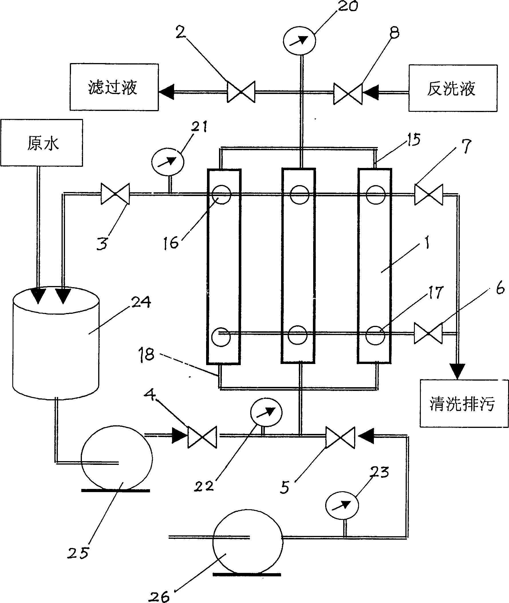
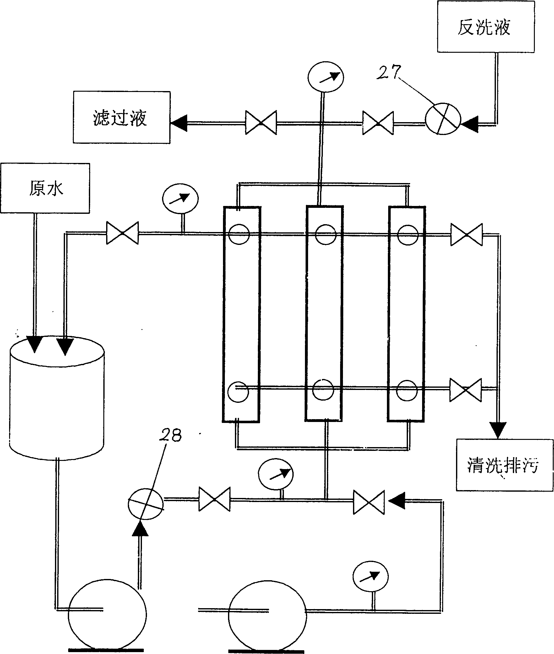
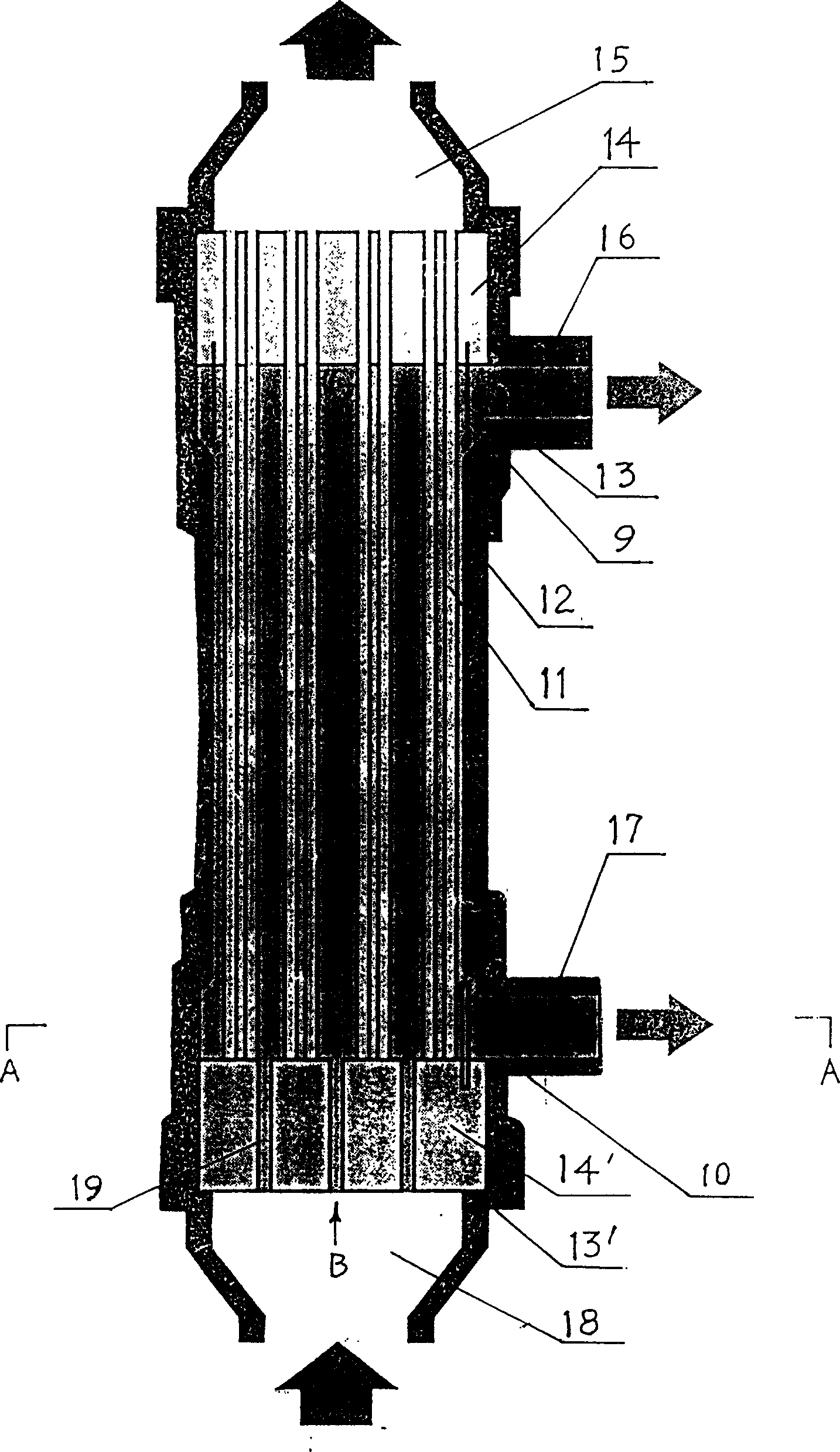
[0015] The device of the present invention is an improved design on the basis of the existing external pressure hollow fiber membrane separation device (hereinafter referred to as the membrane device) (see figure 1 , 3 ), the original membrane device design includes a membrane module 1, a control valve, a pressure gauge, a pump, an air compressor, a feed liquid tank, and connecting pipelines, etc., and the external pressure hollow fiber membrane 11 filled in the membrane module 1 is There are holes at the upper casting end 14, and closed holes at the lower casting end 14', and there are a plurality of diversion holes 19 on the lower casting end 14'. The lower port 18 of the membrane module 1 is passed through the pressure gauge After 22, one path is connected to the pump 25 through the control valve 4, and the other path is connected to the air compressor 26 through the control valve 5, the pressure gauge 23. The characteristic design is that the upper port 15 of the membrane ...


PUM


Abstract

The external pressure hollow fibre membrane separation equipment incldues the common parts of membrane component, etc. and the interior of said membrane component is equipped with packed membrane whose upper casting end has opened hole and lower casting end has closed hole, several guide holes are set on the lower casting end, and one path of lower end hole of said membrane component is connected with pump by means of pipe, and its another path is connected with air compressor by means of pipe. It is characterized by that the upper end hole of membrane component is passed through pressure gauge, then its one path is passed through control valve, and is connected with filtrate tank via pipe, and another path is passed through control valve, and is connected with back-flushing liquid tank via pipe, and one path of upper side hole of the membrane component is passed through pressure gauge and control valve, and is connected with feed liquid tank by means of pipe, and its another path is passed through control valve, and is connected with blow-off pipeline, and the lower side hole also is connected with blow-off pipeline.

Description

technical field [0001] The invention relates to an external-pressure hollow fiber membrane separation device and its application method. The main international patent classification numbers are intended to be Int.Cl7.B01D 6 / 02, B01D 65 / 02. Background technique [0002] Water is the source of life. With the improvement of living standards, on the one hand, people's requirements for drinking water continue to increase. The so-called pure water, space water or purified water has entered people's daily life. On the other hand, production and industrial water such as biochemical, pharmaceutical, food, seasoning and other fields have higher and higher requirements for water purity or clarity. In recent years, people have developed microfiltration and ultrafiltration membrane technology for water purification, which is meeting this need and has achieved good practical results. Among them, external pressure hollow fiber membranes are most widely used. This is because the externa...

Claims


Application Information

Patent Timeline
IPC IPC(8): B01D61/18B01D61/20B01D63/02B01D65/02
Inventor 吕晓龙
Owner TIANJIN MOTIMO MEMBRANE TECH
Learn More