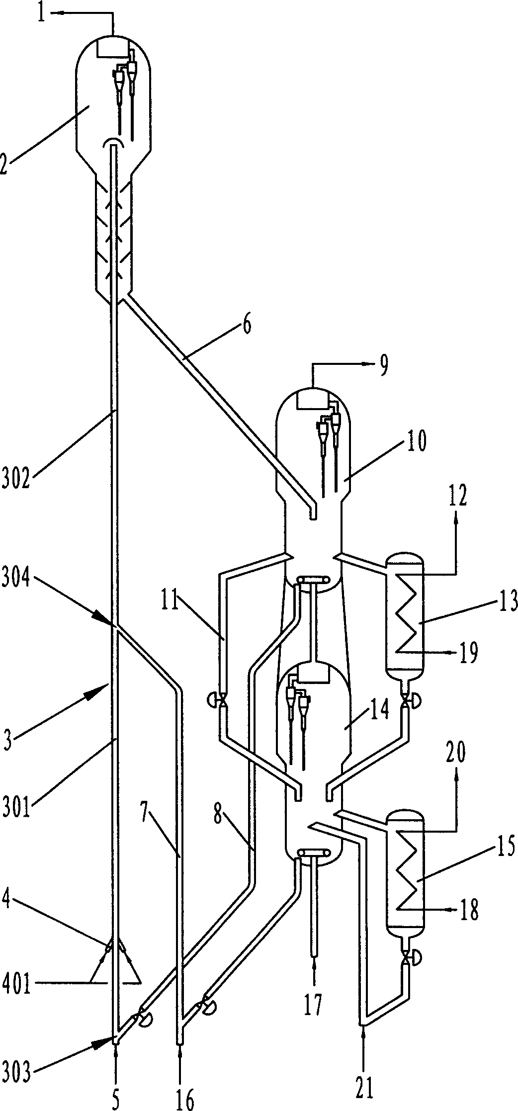
Lift pipe catalytic cracking method and device
A catalytic cracking device and catalytic cracking technology, applied in catalytic cracking, cracking, petroleum industry, etc., can solve the problems that the catalyst activity is not fully utilized, the stripping effect is affected by the amount of stripping steam, and the thermal cracking reaction effect is exacerbated. , to achieve the effect of reducing thermal cracking effect, improving product quality and improving product distribution
- Summary
- Abstract
- Description
- Claims
- Application Information
AI Technical Summary
Problems solved by technology
Method used
Image
Examples
Embodiment 1
[0042] This example illustrates the results of catalytic cracking using Daqing atmospheric residue as feedstock oil. The distance from the catalyst inlet of the second reaction section (that is, the catalyst inlet in the middle of the riser reactor) to the catalyst inlet at the bottom of the riser reactor is 50% of the total length of the riser reactor. Table 2 gives the specific data of product distribution and gasoline quality, and the comparative data of conventional riser is also given in the table.
[0043]The operating conditions adopted in this embodiment are: the regeneration temperature of the first regenerator is 700°C, the carbon content of the regenerated semi-regenerated catalyst is 0.25w%, and the carbon content of the semi-regenerated catalyst entering the first reaction section from the bottom of the riser reactor is The temperature is 700°C. The regeneration temperature of the second regenerator is 520°C, the carbon content of the regenerated catalyst is 0.05...
Embodiment 2
[0047] This example illustrates the cracking results using Zhongyuan Atmospheric Residue as feedstock oil. The difference from Example 1 is that the distance from the catalyst inlet of the second reaction zone to the catalyst inlet at the bottom of the riser reactor is 40% of the total length of the riser reactor.
[0048] The operating conditions used in this embodiment are: the regeneration temperature of the first regenerator is 705°C, the carbon content of the regenerated semi-regenerated catalyst is 0.20w%, and the carbon content of the semi-regenerated catalyst entering the first reaction section from the bottom of the riser reactor is The temperature was 705°C. The regeneration temperature of the second regenerator is 510°C, the carbon content of the regenerated catalyst is 0.05w%, and the temperature of the regenerated catalyst entering the second reaction section of the riser reactor is 510°C. The reaction conditions of the first reaction section of the riser reactor...
Embodiment 3
[0054] This example illustrates the cracking results of using the atmospheric residual oil from the Luning pipeline as the feedstock. The distance from the catalyst inlet of the second reaction section to the catalyst inlet at the bottom of the riser reactor is 65% of the total length of the riser reactor.
[0055] The operating conditions used in this embodiment are: the regeneration temperature of the first regenerator is 705°C, the carbon content of the regenerated semi-regenerated catalyst is 0.20w%, and the carbon content of the semi-regenerated catalyst entering the first reaction section from the bottom of the riser reactor is The temperature was 705°C. The regeneration temperature of the second regenerator is 510°C, the carbon content of the regenerated catalyst is 0.05w%, and the temperature of the regenerated catalyst entering the second reaction section of the riser reactor is 510°C. The reaction conditions of the first reaction section of the riser reactor are as ...
PUM
 Abstract
Description
Claims
Application Information
 - R&D
- Intellectual Property
- Life Sciences
- Materials
- Tech Scout
- Unparalleled Data Quality
- Higher Quality Content
- 60% Fewer Hallucinations
Browse by: Latest US Patents, China's latest patents, Technical Efficacy Thesaurus, Application Domain, Technology Topic, Popular Technical Reports.
© 2025 PatSnap. All rights reserved.Legal|Privacy policy|Modern Slavery Act Transparency Statement|Sitemap|About US| Contact US: help@patsnap.com

