Ring magnet and its loudspeaker
A loudspeaker, ring magnet technology, applied in the direction of sensors, inductors/transformers/magnets, magnetic materials, etc., can solve the problems of insufficient linearity and/or peak value, difficulty, and practicality of increasing the thrust of the voice coil.
- Summary
- Abstract
- Description
- Claims
- Application Information
AI Technical Summary
Problems solved by technology
Method used
Image

Examples
Embodiment 1
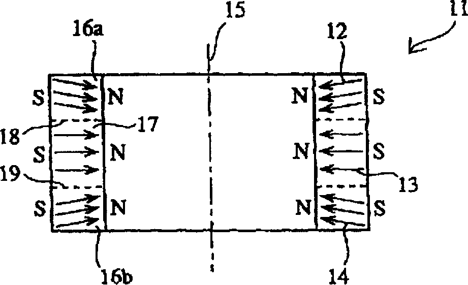
[0049] Nd, Dy, the total weight of B and Fe are counted as 100%, and the alloy coarse powder with 30.5% Nd-1.5% Dy-1.1% B-the rest being Fe (weight %) as the main component is in an inert atmosphere. Jet powder machine pulverized into fine powder, made into fine powder with an average particle diameter of 4.3 μm. These powders were filled in a mold (not shown in the figure), and subjected to heat treatment by compression molding while applying a magnetic field oriented in the radial direction corresponding to FIG. 1 . at about 7 x 10 -2 Pa (about 5×10- 4 The obtained molded body was sintered by heating at 1100° C. for 2 hours in a vacuum of Torr), and then cooled to room temperature. Next, after heating at 900° C. for 2 hours in an Ar atmosphere, it was cooled to 600° C., and then, after heating at 600° C. for 2 hours, it was cooled to room temperature. The obtained sintered body is processed into a prescribed ring shape, after which thermosetting epoxy resin is deposited o...
Embodiment 2
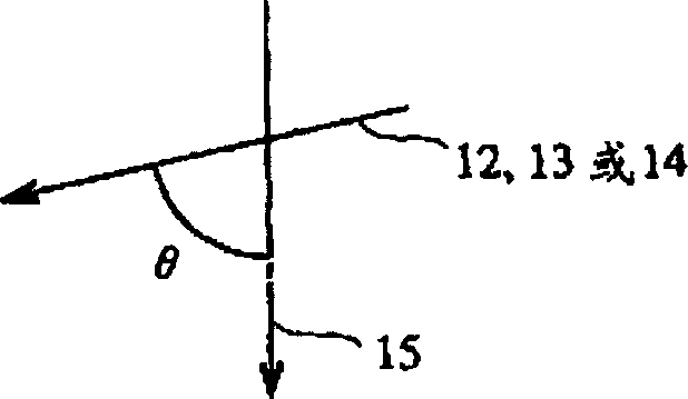
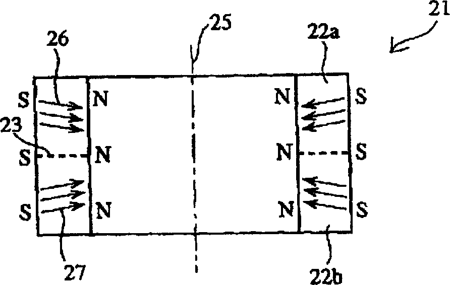
[0053] In addition to the applied magnetic field during compression molding as a corresponding figure 2 Except for the radial orientation magnetic field, the ring magnet 21 was produced and evaluated in the same manner as in Example 1. figure 2 In , the central axis is identified by 25 , the boundaries of the regions 22a and 22b are identified by 23 , and the average magnetic field lines are identified by 26 . According to the magnetic field analysis results, as shown in Table 1, the ring magnet of this embodiment has figure 2 This can be clearly seen in the radially anisotropic region shown.
Embodiment 3
[0061] For the speaker 50 shown in FIG. 4( a ), as shown in FIG. 4( b ), the gap magnetic flux density in the magnetic gap 57 was measured when moving up and down from the center position O of the magnetic gap 57 . There is a center position O on the extension line of the center line 60 which divides the ring magnet 11 into two parts in the axial direction. The measurement results are shown in Figure 5 middle.
PUM
| Property | Measurement | Unit |
|---|---|---|
| thickness | aaaaa | aaaaa |
Abstract
Description
Claims
Application Information
 - R&D
- Intellectual Property
- Life Sciences
- Materials
- Tech Scout
- Unparalleled Data Quality
- Higher Quality Content
- 60% Fewer Hallucinations
Browse by: Latest US Patents, China's latest patents, Technical Efficacy Thesaurus, Application Domain, Technology Topic, Popular Technical Reports.
© 2025 PatSnap. All rights reserved.Legal|Privacy policy|Modern Slavery Act Transparency Statement|Sitemap|About US| Contact US: help@patsnap.com