Automatic flatness measuring device and method

A technology of automatic measurement and flatness, applied in the direction of length measuring device, metal processing equipment, metal rolling, etc., can solve the problems of low efficiency, long downtime occupied by measurement, high labor intensity, etc., and achieve high efficiency and measurement The effect of high speed and reduced labor intensity

Inactive Publication Date: 2006-11-01
张学庄 +1
View PDF4 Cites 0 Cited by
  • Summary
  • Abstract
  • Description
  • Claims
  • Application Information

AI Technical Summary

Problems solved by technology

[0007] The purpose of the present invention is to solve the problem of automatic measurement of the flatness of plates, especially thin metal plates, and to solve the problem of high labor intensity when manually measuring the flatness in the high-temperature environment of a rolling mill, the long downtime of the measurement, and the high efficiency. low level problem

Method used


Image

  • Automatic flatness measuring device and method
  • Automatic flatness measuring device and method
  • Automatic flatness measuring device and method

Examples


Embodiment 1

[0061] The flatness of the plate is measured with a laser flatness automatic measuring device.

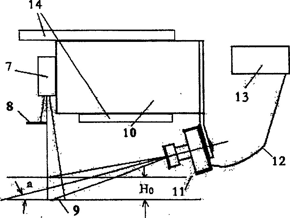
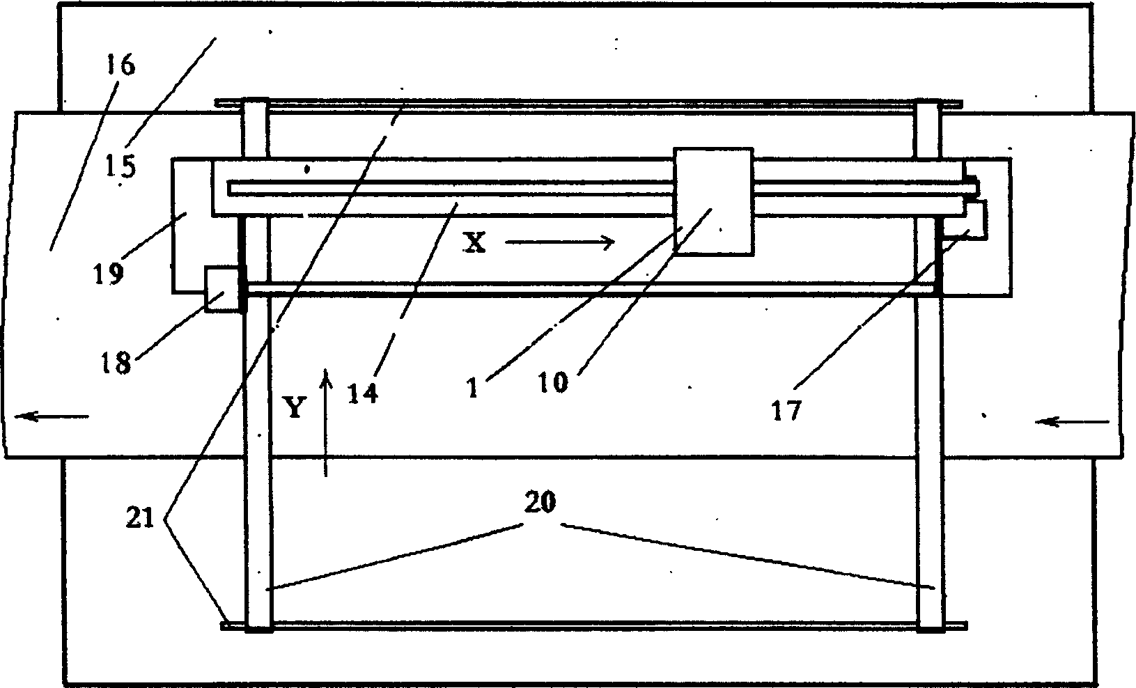
[0062] The semiconductor laser beam expansion light source adopts a 2mW semiconductor laser 7, which is fixed on the probe slider 10. The laser optical axis is perpendicular to the measurement platform 15 plane, and the diameter of its divergent light spot on the measurement platform 15 far away from 90mm is about 33mm; on the optical path A light blocking plate 8 is set at 22mm away from the measuring platform 15 (22mm is greater than Ho), so that the light spot just becomes a semicircle, and the diameter is parallel to the X guide rail 14; on the probe slider 10, a bracket is used to fix the black and white CCD camera 11, Its model is BL-210B, 420 lines, equipped with an 8mm lens, the a angle is about 24 degrees, and the distance from the center of the laser spot is about 60mm. The output of the CCD camera 11 is sent to the VT-210 video image acquisition card 13 inserted in the P...

Embodiment 2

[0072] The laser flatness automatic measuring device measures the plate.

[0073]It is characterized in that 23 lasers 25 are installed on the measuring frame 29, and they are vertically projected on the plate to be measured. The light blocking plate 32 adopts a stainless steel alloy ruler with a smooth edge, which is perpendicular to and intersects with the optical axes of the lasers 25 . The light spot projected by each laser on the measuring plate is a semicircle, and the diameter image is a straight line. 23 BL-210B CCD camera heads 11 with 8mm lens are arranged closely in a line on the measurement frame 29, and the angle a of the installation is about 24 degrees. Each CCD camera is about 60 mm away from the center of the laser spot of the corresponding laser 7 . Each camera 11 picks up a small segment of images in the X direction of the survey line, and 23 CCD cameras 11 can measure the wave shape of the 690mm long survey line in the X direction. The output of each CCD...


PUM


Abstract

The invention relates to an instrument characterized by optical measurement method, which is an automatic flatness measurement method and device, especially a laser flatness automatic measurement system for measuring and inspecting thin steel plates, characterized in that: a laser wave shape measurement sensor (1) consists of semiconductor laser (7), light blocking plate (8), CCD camera (11), image acquisition card (13) and probe slider (10), etc., the image acquisition card (13) is inserted into the computer In (4), the probe slider (10) fixes the laser (7) and the CCD camera (11), and carries them to slide on the X-direction guide rail (14). The invention can measure the flatness of plates with various thicknesses, the measuring process is fully automated, the measuring precision is high, the speed is fast, the production line pause time is short, and the efficiency is high, and it can be flexibly used for product inspection of production sites and steel plate users.

Description

Technical field: [0001] The invention relates to an instrument characterized by an optical measurement method, and is an automatic flatness measurement method and device, especially a laser flatness automatic measurement system for measuring and inspecting thin steel plates. Background technique: [0002] In various places of industry, national defense, scientific research, and production, such as aircraft, rockets, submarines, automobiles, refrigerators, instrument racks, and even cans, etc., plates are used. The flatness of the surface of the plate (also known as unevenness or convexity) degrees) have different requirements and even strict requirements. Therefore, the inspection of flatness in the production and use departments is very important. However, the currently known flatness measurement is carried out by manual methods using relatively simple tools. For example, some large iron and steel enterprises in China use advanced imported production lines and testing equi...

Claims


Application Information

Patent Timeline
Patent Type & Authority Patents(China)
IPC IPC(8): B21B38/02
Inventor 张学庄张驰
Owner 张学庄
Why Eureka
Try Eureka