Phase detector

A phase detector and phase technology, applied in mutually independent oscillating circuits, automatic power control, electrical components, etc., can solve the problems of increasing circuit scale and current consumption, increasing reference frequency, etc., to increase circuit scale and current consumption. , the effect of reducing the impact

Inactive Publication Date: 2001-04-25
UNWIRED PLANET
View PDF1 Cites 5 Cited by
  • Summary
  • Abstract
  • Description
  • Claims
  • Application Information

AI Technical Summary

Problems solved by technology

However, introducing, such as a frequency multiplier to increase the reference frequency and reduce the influence of noise, requires additional circuitry, and increases the scale and current consumption of the circuit

Method used


Image

  • Phase detector
  • Phase detector
  • Phase detector

Examples


Embodiment Construction

[0015] DETAILED DESCRIPTION OF THE PREFERRED EMBODIMENT

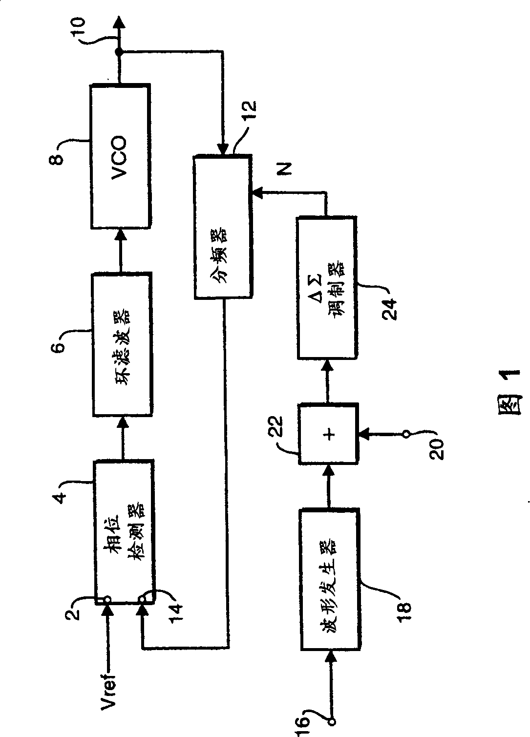
[0016] Figure 1 is a block diagram of a fractional-N phase-locked loop circuit, in this example a delta-sigma modulator is used to control the frequency division as used in the transmit circuit of a mobile communication device such as a mobile phone The frequency division factor of the device. A similar circuit can be used to control the local oscillator frequency in the receive circuit of such a device.

[0017] Usually as a convention, with a reference frequency f ref The input reference signal V ref is supplied to the first input 2 of the phase detector 4 . The output of phase detector 4 is filtered in loop filter 6 and passed to a voltage controlled oscillator (VCO) 8 providing an output signal on loop output 10 . The output signal of the VCO 8 is also supplied to the frequency divider 12, where it is divided by the frequency division ratio N. The frequency-divided output of the frequency divider 12 is supplied...


PUM


Abstract

There is disclosed a phase detector which triggers on both rising and falling edges of an input pulse signal. This effectively doubles the frequency of the input signal. When the phase detector is used in a phase locked loop, the doubled frequency means that a lower division ratio can be used, thereby reducing any noise contribution introduced thereby.

Description

[0001] technical field of invention [0002] The present invention relates to a phase detector circuit, and more particularly to a phase detector which can be used in a phase-locked loop. More specifically, the present invention relates to a phase detector that is triggered on both edges of a system clock, thereby effectively doubling the reference frequency without adding circuitry and noise. Background of the invention [0003] In digital communication systems, such as mobile telephone communications operating under the GSM or DCS systems, continuous phase modulation (CPM) techniques are used. [0004] Phase locked loops are well known. A signal with a reference frequency provides the input to the phase detector, and the output of the phase detector is filtered and sent to the voltage controlled oscillator. The output of the voltage controlled oscillator is the output of the phase locked loop and is also fed back to the frequency divider. The output of the frequency divid...

Claims


Application Information

Patent Timeline
Patent Type & Authority Applications(China)
IPC IPC(8): H03D13/00H03L7/085H03L7/089H03L7/183H03L7/197
CPCH03L7/1976H03D13/004H03L7/0891H03L7/0898H03L7/0896H03D13/00
Inventor B·林德奎斯特M·尼尔松
Owner UNWIRED PLANET
Why Eureka
Try Eureka