Pyrolysis heater with paired burner zoned firing system

A technology of burners and heaters, applied in electric furnace heating, lighting and heating equipment, preheating costs, etc.

Inactive Publication Date: 2007-03-28
ABB LUMMUS GLOBAL INC
View PDF5 Cites 1 Cited by
  • Summary
  • Abstract
  • Description
  • Claims
  • Application Information

AI Technical Summary

Problems solved by technology

In typical radiant coils, operation is limited by the maximum metal temp...

Method used


Image

  • Pyrolysis heater with paired burner zoned firing system
  • Pyrolysis heater with paired burner zoned firing system
  • Pyrolysis heater with paired burner zoned firing system

Examples


Embodiment Construction

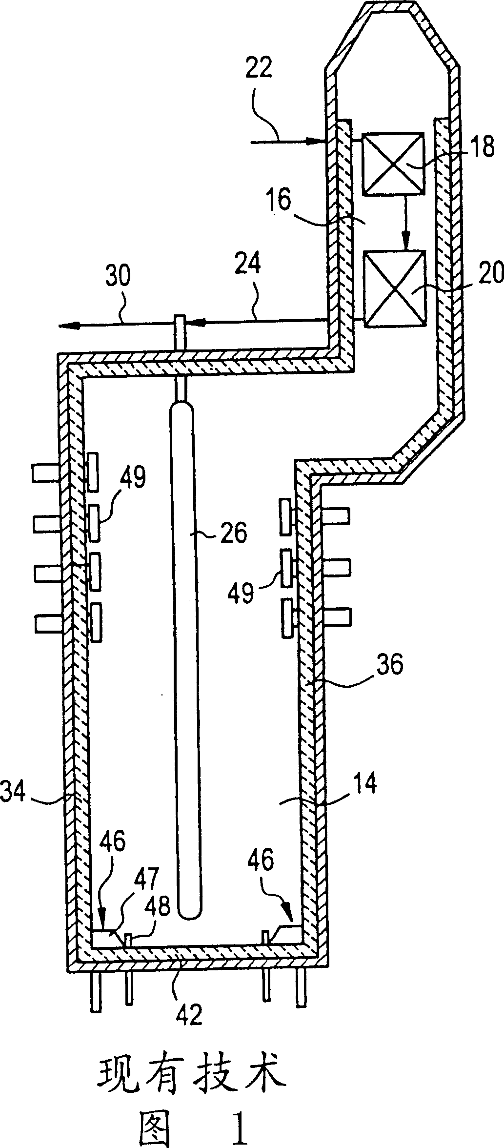
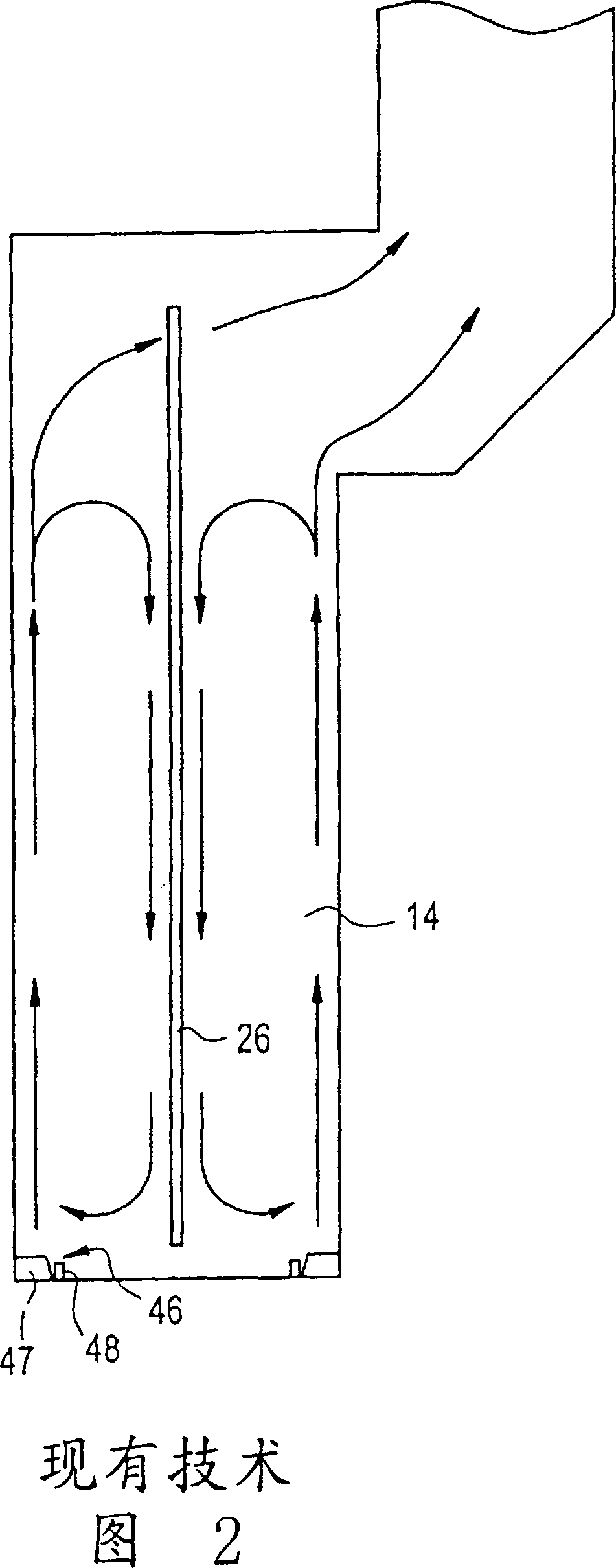
[0019] Before describing the preferred embodiment of the present invention in detail, the pyrolysis heater in the prior art will be described. Figure 1 is a sectional view of such a prior art heater. This heater has a radiant heating zone 14 and a convective heating zone 16 . Heat exchange surfaces 18 and 20 are disposed in convective heating zone 16, the heat exchange surfaces shown here for preheating the hydrocarbon feed. This area may also include heat exchange surfaces for steam generation. Preheated material exiting the convective heating zone is directed along 24 into heating coils 26 located in the radiant heating zone 14 . The cracked products from heating coil 26 are discharged along 30 .

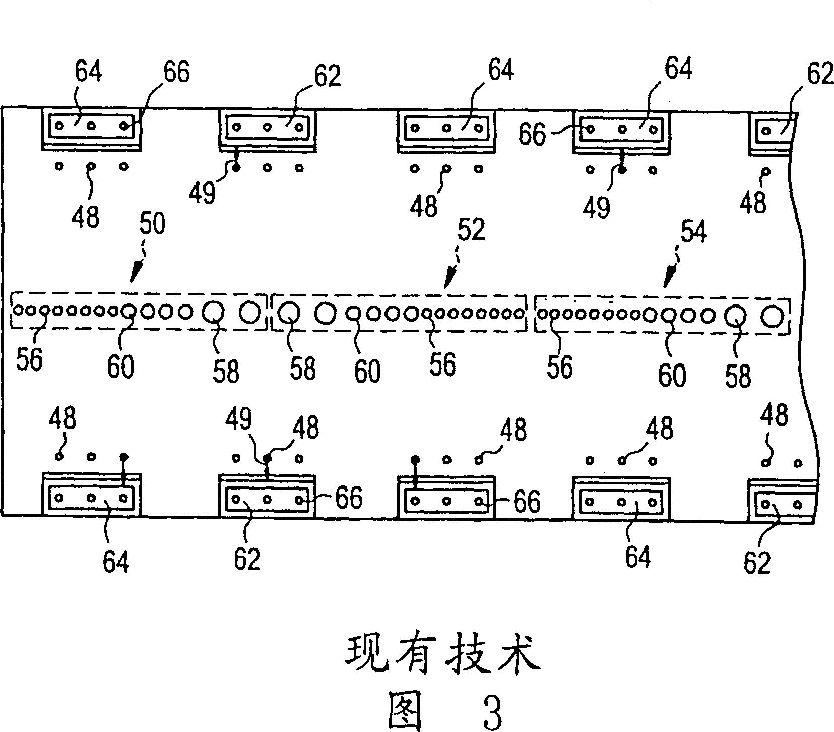
[0020] The radiant heating zone 14 includes walls 34 and 36 and a floor or hearth 42 . Vertically fired hearth burners 46 are mounted on the floor. These burners 46 generally include refractory tiles 47 through which all vertically fed combustion air passes and a series of fu...


PUM


Abstract

A pyrolysis heater has the inlet sections of the process coils grouped together and the outlet sections of these same process coils also grouped together. High heat liberation hearth burners are located adjacent to the inlet sections of the coils and lower heat liberation burners are located adjacent to the outlet sections. The secondary fuel tips of the burners are inclined toward the adjacent, heater wall. The high heat liberation hearth burners adjacent to the inlet coils are arranged in spaced apart pairs with the secondary burner tips of each of the pair being inclined toward the other burner of the pair.

Description

technical field [0001] This invention relates to pyrolysis heaters and in particular to an improved burner arrangement for controlling heat flow to different sections of a process coil. Background technique [0002] A typical pyrolysis heater consists of one or more combustion chambers consisting of a radiant heating section and one or more upper convective sections including a material preheater. The radiant heating section includes a plurality of radiant process coils suspended at the center plane between the two radiant walls of the combustion chamber. The channels of each row of coils are mostly forged as tubes that gradually increase in diameter towards the outlet end. Typically coils have a number of parallel smaller tubes at the inlet end and a few larger tubes at the outlet end. [0003] Vertical burners are placed on the hearth or floor of the combustion chamber and these burners are used as heat sources in many types of pyrolysis heaters. In the ethylene crackin...

Claims


Application Information

Patent Timeline
IPC IPC(8): C10G9/16C10G9/20C07C4/04C07C11/02B01J19/00C10G9/18F27D11/02F27D13/00
CPCC10G9/20F27B9/00
Inventor P·J·查普曼E·M·J·普拉特沃特R·J·加特赛德
Owner ABB LUMMUS GLOBAL INC
Why Eureka
Try Eureka