Three-differential focasing micro-three-dimensional super-resolution imaging method

A super-resolution imaging and differential confocal technology, which is applied to the analysis of materials, material analysis through optical means, and measurement devices, etc., can solve the problems of environmental temperature drift, confocal microscope axial tomographic precision restriction, increase, etc. , to achieve the effect of improving the signal-to-noise ratio, enhancing the anti-interference ability of the environment, and improving the defocus characteristics

Inactive Publication Date: 2007-04-11
严格集团股份有限公司
View PDF5 Cites 0 Cited by
  • Summary
  • Abstract
  • Description
  • Claims
  • Application Information

AI Technical Summary

Problems solved by technology

[0004] Generally speaking, the above-mentioned new confocal microscopes and super-resolution methods and technologies have improved the imaging resolution characteristics of confocal microscopes and solved the needs of many confocal microscopes for super-resolution microscopic imaging measurements, but they still have the following problems to be solved urgently : First, the existing various forms of confocal microscopes use the detected light intensity signals to directly perform imaging processing, which are easily affected by factors such as light intensity fluctuations, background light interference, and environmental temperature drift. Confocal microscope imaging The signal-to-noise ratio of the system is low; the second is that the axial tomographic accuracy of the confocal microscope is limited by the nonlinearity of the axial intensity response curve, and the existing super-resolution technology is likely to cause the increase of side lobes and axial response during the super-resolution imaging process. The increase of curve nonlinearity error
However, the three-differential confocal microscopy imaging method is mainly used to improve the axial resolution of the confocal microscope, but fails to improve the lateral resolution of the confocal microscope. The existing super-resolution pupil filter is used for three-dimensional super-resolution of the confocal microscope. When imaging, it is necessary to perform both lateral super-resolution and axial super-resolution, and the effect of three-dimensional super-resolution is usually not particularly significant

Method used


Image

  • Three-differential focasing micro-three-dimensional super-resolution imaging method
  • Three-differential focasing micro-three-dimensional super-resolution imaging method
  • Three-differential focasing micro-three-dimensional super-resolution imaging method

Examples


Embodiment Construction

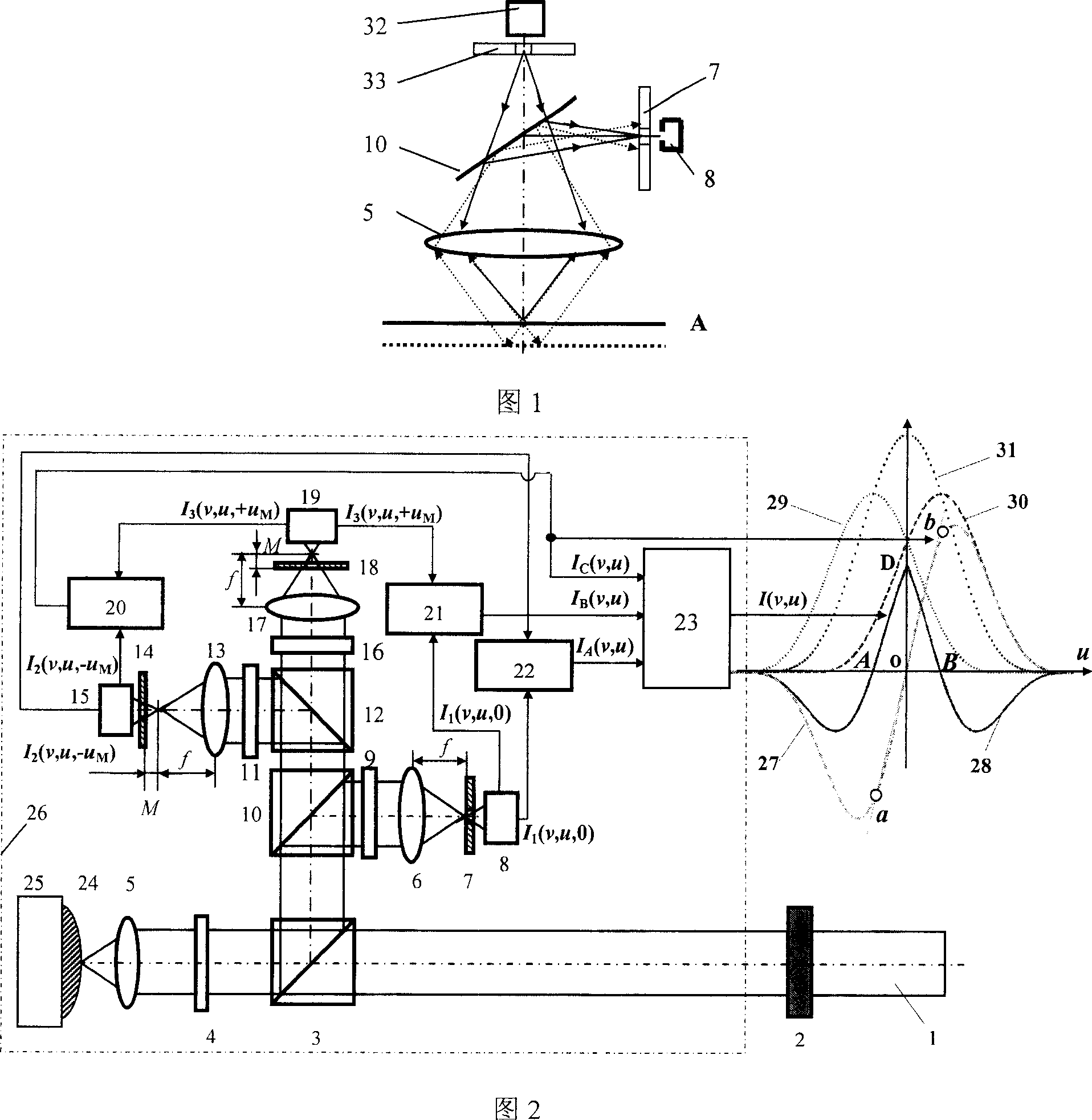
[0035] The three-differential microscopic imaging method of the present invention adopts the three-differential confocal microscopic imaging technology to arrange the receiving optical path of the confocal microscope into a three-way detection optical path of far focus, focal plane and near focus, and detects through the three-way detection system. Three-way intensity response signals with different phases are differentially subtracted in pairs to improve the axial resolution and anti-interference ability. The lateral resolution of the confocal microscope is improved through the super-resolution pupil filter confocal microscopy imaging method, so that Confocal microscopy finally achieves high performance-to-noise ratio and three-dimensional super-resolution microscopic imaging.

[0036] As shown in Figure 2, the virtual frame part 26 is a three-differential confocal microscopic optical path arrangement, and the incident light beam 1 passes through the pupil filter 2 and passes ...


PUM


Abstract

The present invention belongs to the field of optical microscopic imaging and micro measurement technology, and is one 3D three-differential confocal microscopic imaging method with very high S / N ratio and 3D super resolution imaging capacity. The present invention fuses the three-differential confocal scanning method with high axial resolution and pupil filtering confocal scanning method with high transverse resolution to constitute the 3D pupil filtering three-differential confocal microscopic imaging method. The method may be used in measuring 3D surface appearance, 3D fine structure, micro step, micro channel, IC line width, etc.

Description

technical field [0001] The invention belongs to the technical field of optical microscopic imaging and microscopic measurement, and relates to a triple-differential confocal microscopic three-dimensional super-resolution imaging method with high performance-to-noise ratio and three-dimensional super-resolution imaging capability, which can be used to measure three-dimensional surface topography, Three-dimensional microstructure, micro-steps, micro-grooves, integrated circuit line width, etc. Background technique [0002] The idea of ​​confocal microscopy was first proposed by American scholar M.Minsky in 1957, and was authorized by the US patent in 1961, the patent number is US3013467. The confocal microscope places the point light source, point object, and point detector in corresponding conjugate positions, forming a point illumination and point detection microscopic imaging system with unique tomographic capabilities in optical microscopic imaging. The basic principle of...

Claims


Application Information

Patent Timeline
Patent Type & Authority Patents(China)
IPC IPC(8): G01N13/00G01N21/84
Inventor 赵维谦谭久彬邱丽荣
Owner 严格集团股份有限公司
Why Eureka
Try Eureka