

Fuel cell membrane electrode assemblies with improved power outputs
A conductive electrode and electrode technology, applied in fuel cell components, transportation fuel cell technology, fuel cells, etc., can solve unacceptable problems and achieve the effect of precise design and control
- Summary
- Abstract
- Description
- Claims
- Application Information
AI Technical Summary
Problems solved by technology
Method used
Image

Examples
example 1
[0101] Example 1 illustrates an indirect method in which a second catalytically active metal is first deposited on a substrate and then transferred from the substrate to a membrane or electrode.
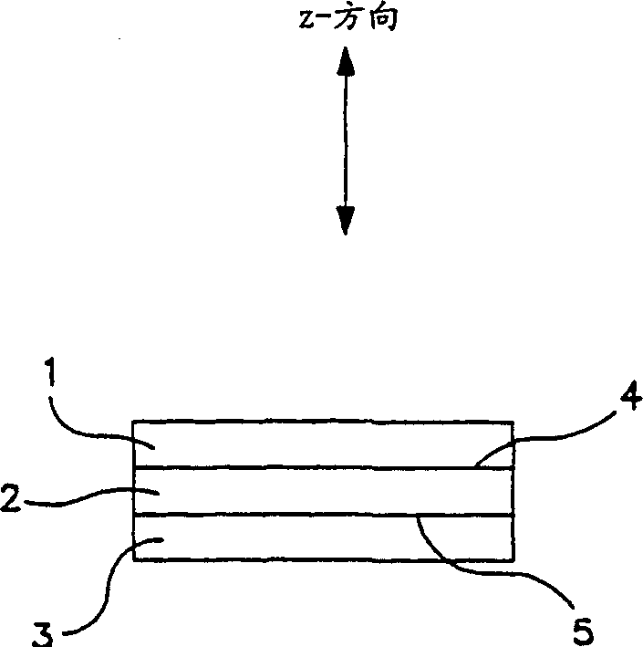
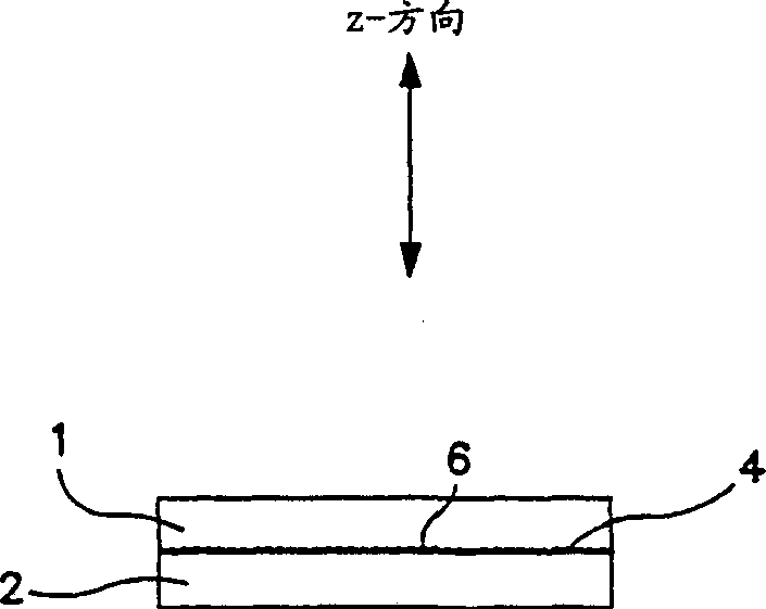
[0102] 50 Å (Angstrom) platinum coating area (0.01mg / cm 2 ) with EB-PVD was deposited at 1 Å / sec onto thinly sliced PTFE substrate substrates. The catalyst area was then transferred to the membrane by embossing such that the 50 Å catalyst area was bonded to one side of the membrane and centered. The area of the membrane occupied by the transferred catalyst is the effective area. Catalyzed electrodes (0.3mg Pt / cm 2 ) was also contacted on each side of the catalyzed membrane using the printing method so as to cover the active area. Thus, one side of the MEA has Z-gradient platinum regions at the membrane / electrode interface.
[0103] Ready with 25cm 2 The effective area of the MEA are packed in 25cm 2 The active area of the fuel is between the gaskets in the test rack or ...
example 2
[0110] In this example, the direct deposition of an area on the electrode is done with a thickness of two areas. Deposition was accomplished with EB-PVD. Before deposition, the catalytic electrode with Z-gradient deposition had 0.1 mg Pt / cm 2 content. For a sample, the deposition rate was 0.2-0.3 Å / sec to achieve a 50 Å area (0.01 mg Pt / cm 2 ). The second electrode was sprayed at a deposition rate of 0.1 Å / sec to achieve a 5 Å area (0.001 mg Pt / cm 2 ). Both samples were used containing 0.05mg / cm 2 Platinum electrode (anode).
[0111] MEA performance was again estimated for cell pressures of 0 psig and 15 psig. For all cases, the cells were operated at a temperature of 65°C, hydrogen and air were supplied at approximately 0 psig, and humidified to a dew point of 60°C. The flow rates of hydrogen and air were 1.2 and 3.5 times, respectively, the stoichiometric equivalents theoretically required to produce a given cell current output.
[0112] Figure 9 shows the improved ...
example 3
[0118] This example illustrates DC magnetron cathodic vacuum sputtering compared to EB-PVD. An electrode (0.4mg Pt / cm 2 ) is coated by DC magnetron cathode vacuum spraying. The goal is 99.9% pure platinum foil with a thickness of 0.127mm, and the base pressure of the vacuum chamber is maintained at 8×10 -4 torr. In particular, established less than 10 -4 torrr's vacuum, and then suck in high-purity argon to raise the pressure to 8×10 -4 torr. The platinum deposition rate was maintained at about 1 Å / sec to obtain 0.01 mg / cm 2 Platinum content (50 Å). This sputtered electrode was used as a cathode. A non-cathode-coated electrode (0.4mg Pt / cm 2 ) as the anode.
[0119] The performance of the MEA was estimated at 0 psig and at 15 osig for cell pressure. For the case of 0 psig cell pressure, the cell was operated at 70°C with both hydrogen and air supplied at 0 psig, humid to dew points of 55°C and 70°C, respectively. In the case of 15 psig the cell was operated at a tem...
PUM
| Property | Measurement | Unit |
|---|---|---|
| width | aaaaa | aaaaa |
| particle size | aaaaa | aaaaa |
| thickness | aaaaa | aaaaa |
Abstract
Description
Claims
Application Information