
Radio communication system and communication terminal apparatus used therein

A technology of a wireless communication system and a communication terminal, which is applied in the field of communication terminal devices and can solve problems such as transmission rate reduction

Inactive Publication Date: 2002-11-20
PANASONIC CORP
View PDF1 Cites 8 Cited by
  • Summary
  • Abstract
  • Description
  • Claims
  • Application Information

AI Technical Summary

Problems solved by technology

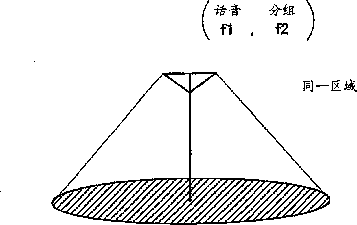
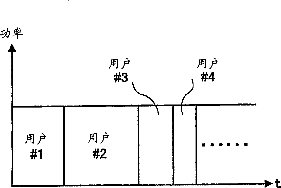
[0008] As described above, in the HDR system, there is a problem that although a high transmission rate (throughput) can be ensured near the base station, the transmission rate decreases as it approaches the edge of the coverage area
On the contrary, in order to maintain the average throughput of each channel, since too many users cannot be accommodated in the limited carrier frequency, it is necessary to limit the number of channels (number of users)

Method used


Image

  • Radio communication system and communication terminal apparatus used therein
  • Radio communication system and communication terminal apparatus used therein
  • Radio communication system and communication terminal apparatus used therein

Examples


Embodiment 1

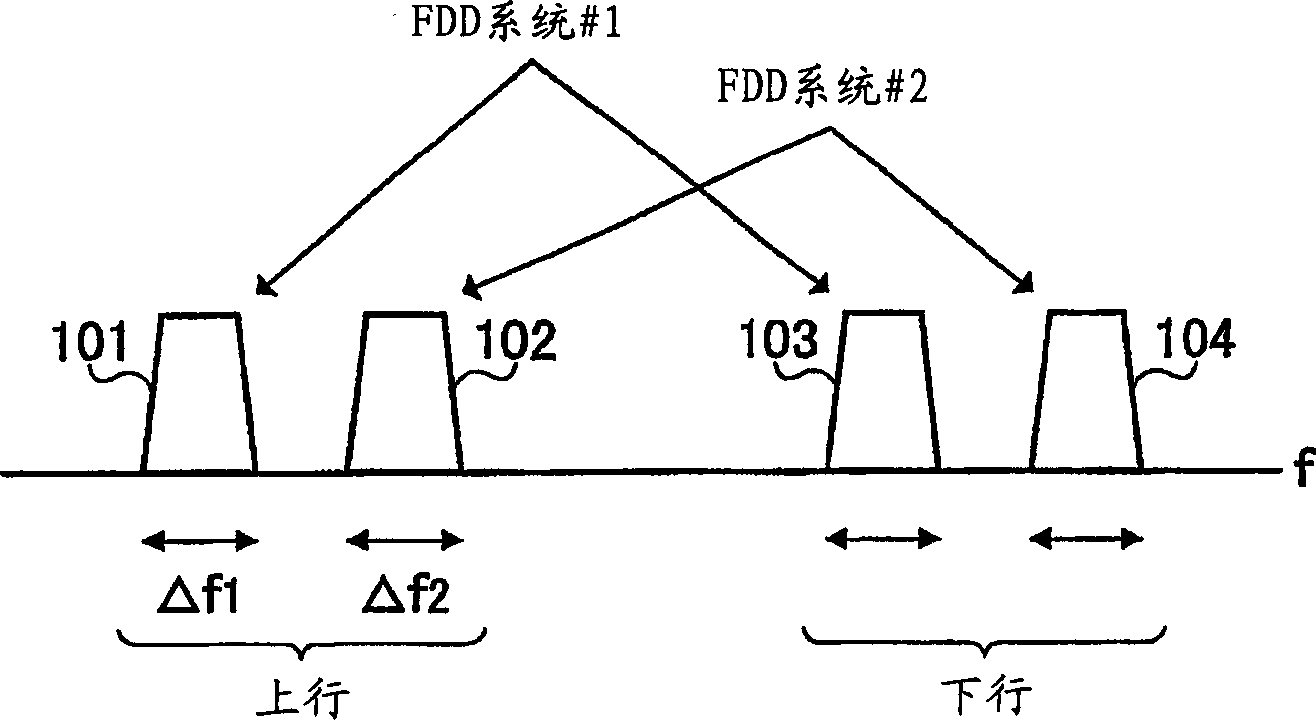
[0032] In this embodiment, in the case of using two systems, the FDD system and the TDD system, as Figure 4 As shown, in the FDD system, a pair of frequency bands (paired bands) are secured by using the uplink and downlink, while in the TDD system, a common frequency band is secured by using the uplink and downlink. That is, the FDD system #3 secures an uplink frequency band 105 and a downlink frequency band 106 as a pair, and TDD system #4 secures a frequency band 107 for uplink and downlink use. The FDD system and the TDD system may each have a plurality of frequency bands.

[0033]In this embodiment, it will be described that a high-speed packet transmission service is accommodated in a TDD system that realizes asymmetric transmission with a slot length longer than that of the downlink and uplink, and that a voice service is accommodated in an FDD system. Or low-speed packet (not high-speed packet) transmission service, the TDD system uses the frequency f2, and the FDD sy...

Embodiment 2

[0072] In this embodiment, a case will be described in which the mobile station reports the measurement result of the communication environment or moving speed and the desired connection to one system, and determines the connection based on the judgment of the base station side to perform communication.

[0073] Figure 9 It is a block diagram showing the configuration of a base station apparatus in the radio communication system according to Embodiment 2 of the present invention.

[0074] First, as described in Embodiment 1 above, a control signal (desired connection information) indicating a desired connection or the measurement result is sent from the mobile station based on the measurement results of each service, communication environment, and moving speed.

[0075] These control signals or signals including measurement results are received via the antenna 401, and predetermined wireless reception processing (down-conversion, A / D conversion, etc.) is performed by the wire...


PUM


Abstract

The base station (BS) 202 receives the voice signal of the FDD system transmitted from the mobile station (MS) 201 as a communication terminal, and sends the received data obtained by performing predetermined processing to the mobile switching station 204 through the wireless network control station 203 . The MSC enables data from several base stations to be aggregated and sent to the telephone line network 207. On the other hand, the high-speed packet of the TDD system transmitted from the mobile station (MS) 201 is received by the base station (BS) 205, and the received data obtained by performing predetermined processing is routed by the router 206 and sent to an IP (Internet Protocol) packet. Net 208.

Description

technical field [0001] The present invention relates to a communication terminal device used in a digital radio communication system. Background technique [0002] With the development of Internet-related technologies in recent years, various services such as music distribution can be provided through the Internet. In such a service, the amount of downlink transmission is very large. In order to realize a service with a large amount of downlink transmission, high-speed packet transmission on the downlink is highly expected. Also, for such high-speed packet transmission in the downlink, various technical developments are underway. [0003] In a cellular system, a system called HDR (High Data Rate) has been proposed as a high-speed packet wireless transmission system. Both the uplink and downlink of this system use the same bandwidth (1.25MHz) as the existing CDMA (Code Division Multiple Access, Code Division Multiple Access) system called IS-95. ...

Claims


Application Information

Patent Timeline
IPC IPC(8): H04B7/26H04W28/06H04W28/22H04W40/02H04W48/16H04W48/18H04W72/04H04W76/02H04W80/00H04W88/02H04W88/08H04W92/14
CPCH04B7/26H04B7/2618H04B2201/70702H04W40/02H04W48/18H04W80/00
Inventor 宫和行
Owner PANASONIC CORP
Learn More