Synchronous gearless permanent-magnet draw machine

A synchronous traction machine and gearless technology, which is applied in the field of traction machines, can solve the problems of low concentricity, affecting the braking effect, and increasing the structural size of the whole machine, so as to achieve high reliability and manufacturability, and improve the air gap The effect of magnetic field waveform and small overall structure size

Inactive Publication Date: 2002-12-25
沈阳蓝光驱动技术有限公司
View PDF0 Cites 11 Cited by
  • Summary
  • Abstract
  • Description
  • Claims
  • Application Information

AI Technical Summary

Problems solved by technology

[0010] (1) As far as the machine base is concerned, the combined structure of the separated parts makes machining relatively more difficult, and the manufacturability is more complicated
This requires not only ensuring the accuracy and tolerance requirements of the assembly dimensions between the various components, but also ensuring the shape and position tolerances of related components, and it is difficult to guarantee the assembly accuracy and concentricity
Especially with the assembly connection structure, not only are there many parts, but the structural size is relatively increased, which increases the manufacturing cost, and the overall mechanical strength is reduced, which will affect the performance and service life of the whole machine
[0011] (2) The fixing of the rotor and the traction wheel adopts the form of assembly connection, which makes the integrity of the traction machine worse and the concentricity is low. In severe cases, the traction machine will not work
When replacing the traction sheave, the whole machine needs to be separated, and the assembly accuracy is difficult to guarantee
Furthermore, due to the assembly and connection method of the traction sheave and the shaft, the distance between the force center of the traction sheave and the support center of the front bearing increases, and the bending strength of the shaft decreases. Once the bolts are loose, the brake fails, and the traction machine will not work , will cause accidents in severe cases
[0012] (3) The overall fixed connection structure of the brake arm and the brake pad not only requires high machining accuracy and poor assembly quality, but also is difficult to adjust when the brake pad and the brake wheel are in poor contact, which affects the braking effect
[0013] (4) The encoder is assembled on the outside of the machine base, which increases the structural size of the whole machine, and the encoder is exposed outside, which is easy to damage

Method used


Image

  • Synchronous gearless permanent-magnet draw machine
  • Synchronous gearless permanent-magnet draw machine
  • Synchronous gearless permanent-magnet draw machine

Examples


Embodiment Construction

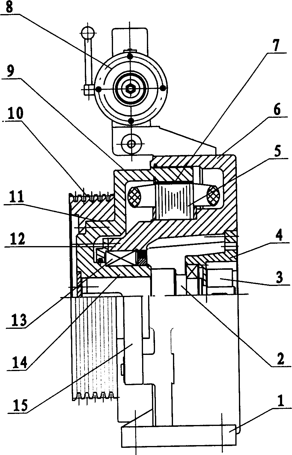
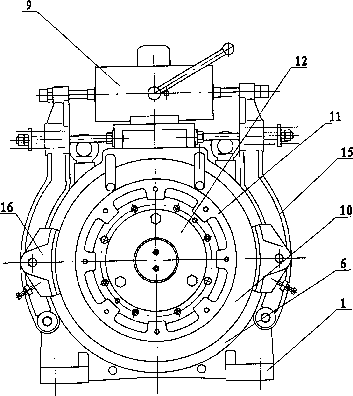
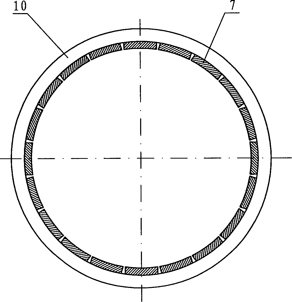
[0027] according to Figure 1-3 The specific structure of the present invention will be described in detail. The device includes a stator, a rotor and a braking device, wherein the machine base 1 is integrally cast with the stator shell 6 and the support sleeve 12, and its specification and shape should be determined according to specific application requirements. The outer peripheral wall 9 of the rotor, the end shoulder 11, and the axle sleeve 14 are cast as a whole. Similarly, its specification and shape should also be determined according to specific use requirements. The inner side of the outer peripheral wall 9 of the rotor is pasted with equal-radius parallel magnetized arc-shaped permanent magnets 7, and its pole arc coefficient is 0.75-0.95. One end of the rotating shaft 2 is fixed in the shaft hole of the rotor shaft sleeve 14, and the other end is assembled in the bearing sleeve 4 by means of a bearing. The stator core 5 is press-fitted on the outer periphery of t...


PUM


Abstract

A permanent magnet synchronous towing machine without gear wheel includes the stator, rotor and the brake equipment. The stator frame, the stator case and the shoring cover are cast as a whole. Arc type permanent magnets are affixed to the inner side of the rotor wall along the direction of circle. Shaft is mounted on the axle hole of the axle housing of the rotor. The iron cords are pressed to the outer side of the shorting cover along direction of the circle. The rotation coder is positioned on the back end of the shaft. The stretch type electromagnetic brake providing thrust in bi-directional is mounted between two brake arms on the base. The brake shoes with hinge jointed on the brake arms are fitted on the symmetrical two sides of the outer wall of the rotor. The towing wheel is fixed on the circular bead of the end part.

Description

technical field [0001] The invention relates to a traction machine for an elevator driving system, in particular to a gearless permanent magnet synchronous traction machine suitable for traction driving of elevators with small machine rooms and machine rooms. The machine can be widely used in other occasions that require low-speed and high-torque operation. Background technique [0002] The traditional elevator drive system mainly adopts the transmission mode of the motor (induction motor) to drive the reducer, which not only has low transmission efficiency, but also increases the volume of the entire drive system due to the existence of the reducer, that is, the transmission power density of the system decreases. At the same time, the defects of the gear itself of the reducer have adverse effects on many technical issues such as low-speed stability and mechanical noise required by the drive system. [0003] With the development of modern control theory and technology and t...

Claims


Application Information

Patent Timeline
Patent Type & Authority Applications(China)
IPC IPC(8): H02K21/22
Inventor 徐广人张盛亮
Owner 沈阳蓝光驱动技术有限公司
Why Eureka
Try Eureka