Engine perfomance monitoring method and monitor

A monitoring device and engine technology, applied in the direction of engine test, measurement device, machine/structural component test, etc., can solve the problems of not being able to be installed on the vehicle, too many sensors, excessive detection, etc., to prevent major accidents and anti-interference ability. Strong, high-precision control effect

Inactive Publication Date: 2003-01-08
石家庄开发区天远科技有限公司
View PDF2 Cites 11 Cited by
  • Summary
  • Abstract
  • Description
  • Claims
  • Application Information

AI Technical Summary

Problems solved by technology

China Patent No. 90215162.2 discloses a microcomputer detection device for an automobile engine, which measures the platinum gap, platinum performance, and distributor drive of the engine ignition system by installing a high-voltage signal, a cylinder ignition signal acquisition sensor and a distributor signal acquisition sensor on the gasoline engine. There are many measurement items for the wear degree of the cam and the working consistency of each cylinder of the engine, but there are also many additional sensors installed, and the detection objects are limited to gasoline engines
[0003] Although the above devices have tested and analyzed several key performance indicators of the engine, the performance of the engine is not only related to the key performance indicators, such as the degree of fuel atomization and fuel quality are also important performance indicators of the engine, which also affect the performance of the engine. Working performance, these indicators cannot be detected more conveniently when the machine is working, so the above-mentioned method of detecting the key performance indicators of the engine cannot fully reflect the working performance of the engine
[0004] In addition, most of the above-mentioned detection instruments are independent detection instruments, which cannot be installed on the vehicle, and can only be tested periodically, which not only causes excessive detection, but also cannot completely prevent the occurrence of failures; some of the existing technologies can be installed on the vehicle, The engine performance detection device that does not affect the mechanical work also has the above-mentioned shortcomings

Method used


Image

  • Engine perfomance monitoring method and monitor
  • Engine perfomance monitoring method and monitor
  • Engine perfomance monitoring method and monitor

Examples


Embodiment Construction

[0035] The principle of the engine performance monitoring method that the present invention proposes is:

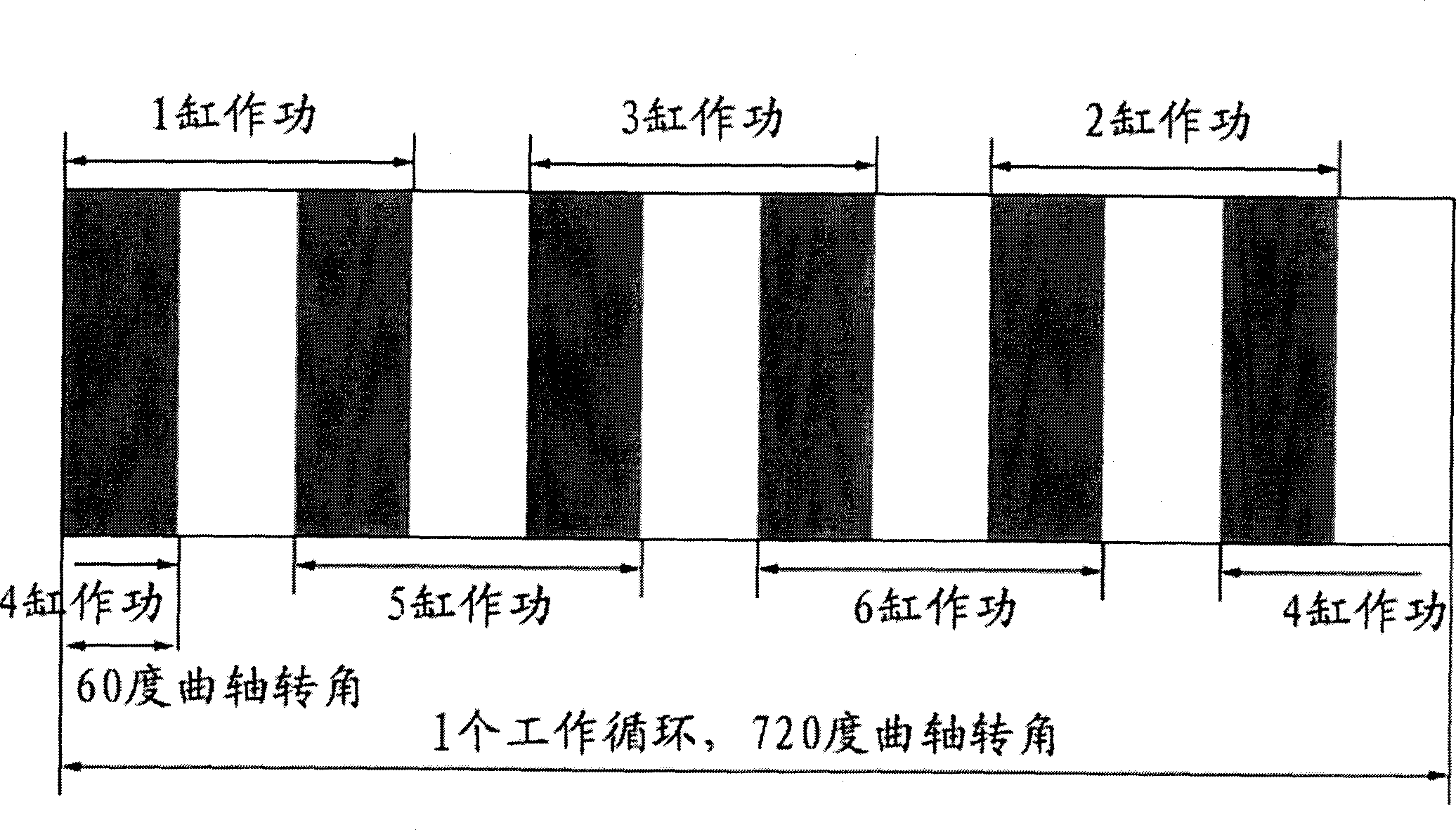
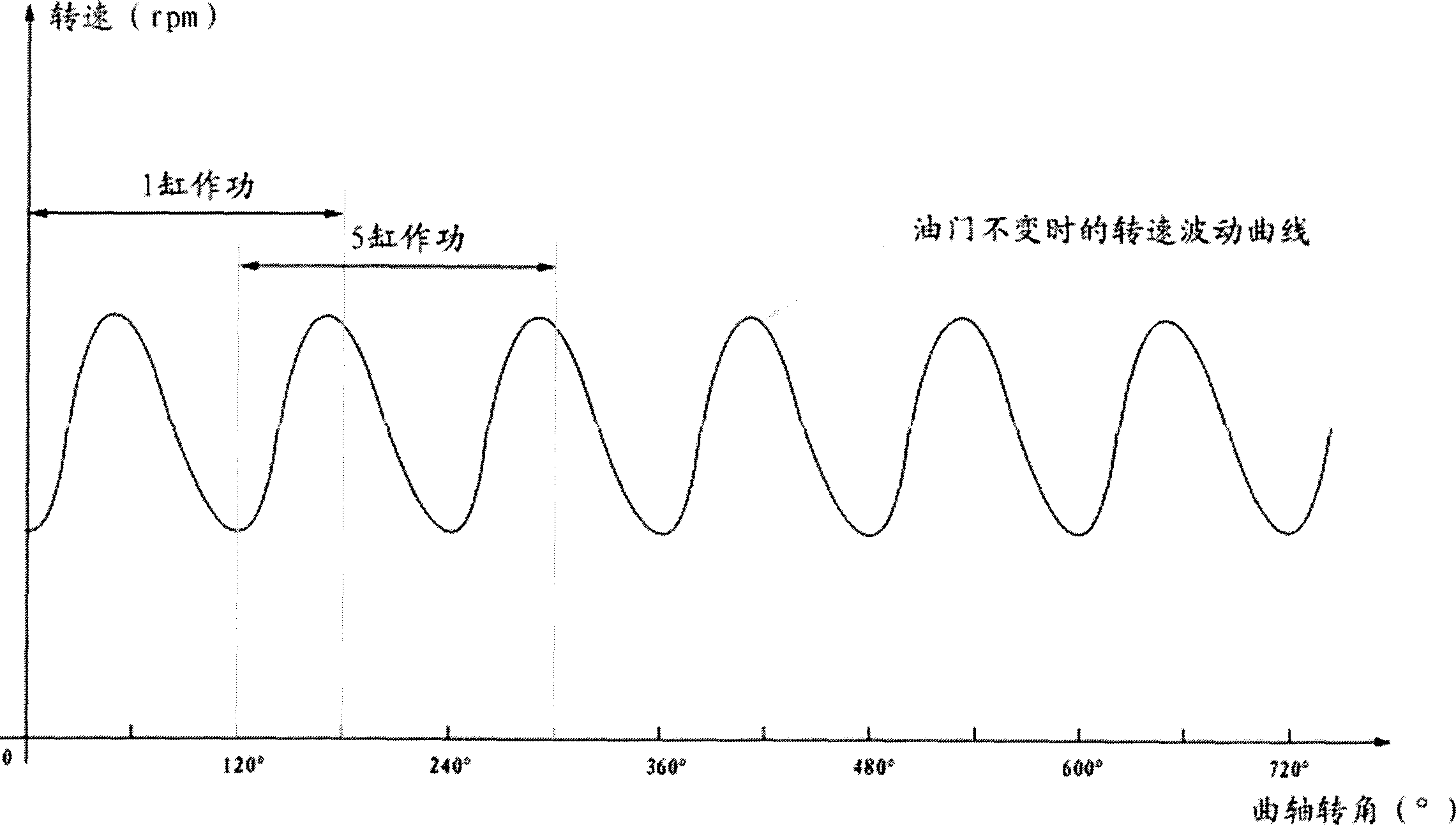
[0036] When the engine is running normally and the throttle is constant, the engine speed does not remain constant, but changes slightly. The reason is that when the engine cylinder works, the combustion gas expands to push the piston, connecting rod, and crankshaft to rotate, so that the engine speed When the cylinder does not work, due to the inertia of the flywheel, the crankshaft drives the piston to rotate, and the speed decreases. The more cylinders of the engine, the smaller the slight difference in the rotational speed between the above-mentioned engine cylinders doing work and not doing work, but due to the overlap of the power strokes, the slight change in the rotational speed when the engine throttle is constant still exists.

[0037] Take an in-line six-cylinder four-stroke internal combustion engine as an example.

[0038] 1. For a six-cylinder four-stroke e...


PUM


Abstract

A monitor method of engine performance is to analyze the raising amplitude of rotating speed of each engine cylinder to decide working performance of the engine. This invention adopts ns-grade gethering and processing circuit with very high gethering accuracy to identify the rotation speed difference among teeth of the engine flywheel and by analyzing amplitude of speed wave pulse of each cylinder in operation to know the working performance of the cylinder and uniform working of each cylinder. The device comprises a rotation speed transducer the output of which is connected with a signal gethering treatment circuit connected with a computer process circuit.

Description

technical field [0001] The invention relates to an engine performance monitoring method and device, belonging to the technical field of engine working condition control. Background technique [0002] At present, there are many engine performance detection devices, mainly relying on the detection of key performance indicators of the engine (such as valve timing, fuel supply / ignition advance angle, fuel supply interval angle, fuel supply uniformity, engine blow-by, etc.) to judge engine performance. This type of device needs to be additionally equipped with a large number of sensors, which undoubtedly increases the cost and reduces the overall reliability. Belonging to this type of device are: Chinese Patent No. 94119157.5 discloses a dynamic engine multifunctional detector, it is through clamping the pressure sensor on the high-pressure oil pipe of the diesel engine, installing a photoelectric sensor above the flywheel, and sticking a scale coding tape on the flywheel. Detec...

Claims


Application Information

Patent Timeline
Patent Type & Authority Applications(China)
IPC IPC(8): G01M15/00
Inventor 韩晓明
Owner 石家庄开发区天远科技有限公司
Why Eureka
Try Eureka