Method and apparatus for particle agglomeration

A technology of particle and ion generator, applied in electrostatic coagulator, a device for condensing particles in gas flow, and promoting the field of small particle coagulation in gas flow, which can solve the problems of increasing equipment size, polluting waste water, and low particle collection efficiency. To achieve the effect of promoting cohesion

Inactive Publication Date: 2003-01-08
HANSOM ENVIRONMENTAL PROD
View PDF2 Cites 26 Cited by
  • Summary
  • Abstract
  • Description
  • Claims
  • Application Information

AI Technical Summary

Problems solved by technology

For particles smaller than 0.1 microns, diffusion is usually the main mechanism of action for particle transport, charging and trapping, however, for particles between 0.1 and 0.2 microns, diffusion, electrostatic and inertial effects are not very strong, known Devices using these principles of action exhibited the lowest collection efficiencies for particles in these size ranges
[0012] The effect of diffusion trapping can be improved by providing a large surface area and / or more time for diffusion to occur, but this requires a substantial increase in device size
Larger inertial forces can be obtained by increasing the relative velocity of the particles relative to the collection surface, but at the expense of larger pressure differences and energy input to the collection device, which will result in a significant increase in cost
Therefore, economic considerations limit the application of these methods
[0013] Other dust collection devices used for fine particle emission control include wet electrostatic precipitators and wet precipitators, which generally require large and expensive equipment and create problems with polluting wastewater
Fiber filters have also been used as dust collectors, but they are generally ineffective collectors for fine particles because these small and often smooth particles tend to flow through the fabric used in such filters

Method used


Image

  • Method and apparatus for particle agglomeration
  • Method and apparatus for particle agglomeration
  • Method and apparatus for particle agglomeration

Examples


Embodiment Construction

[0041] Description of preferred embodiments

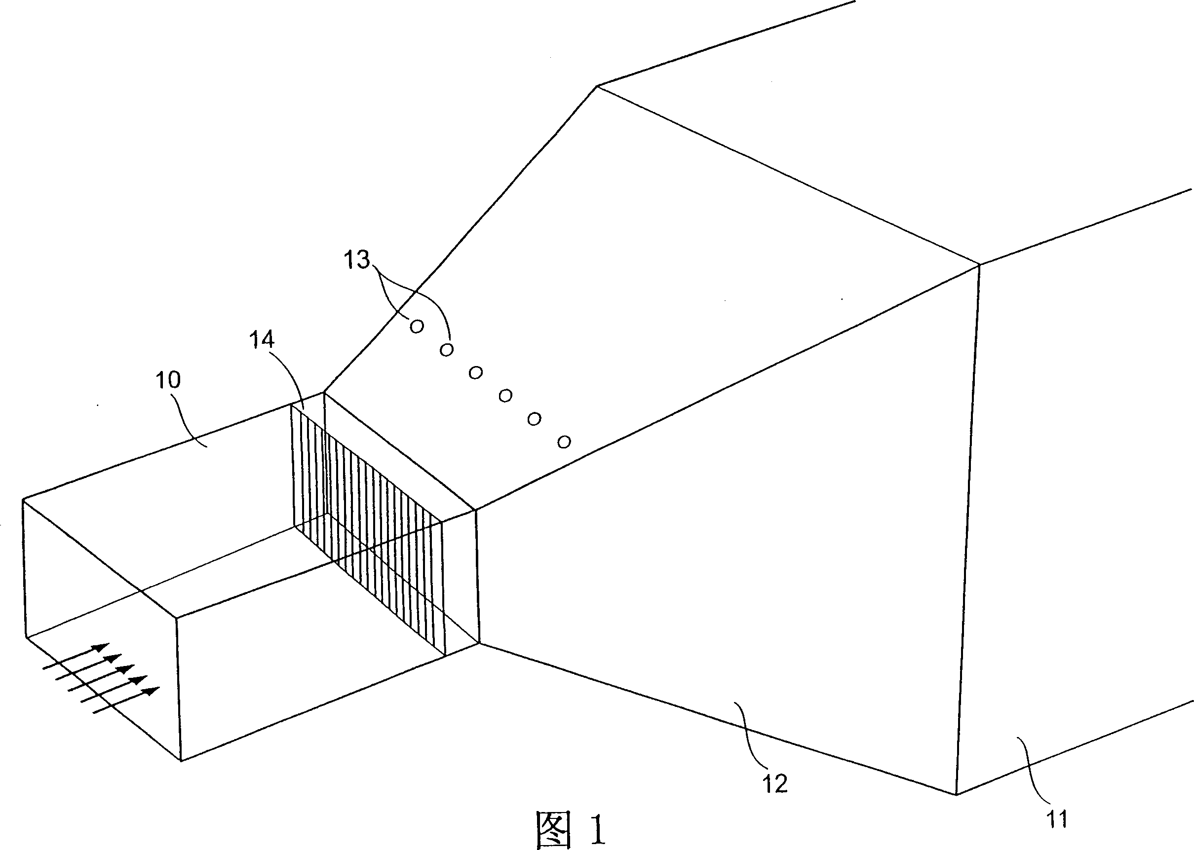
[0042] Figures 1-3 show the first embodiment of the particle aggregation device of the present invention. In this embodiment, pre-charged particles of different sizes in the air stream are made to have different velocities in order to improve the mixing of the particles in the longitudinal direction of motion. This increased mixing leads to agglomeration of particles.

[0043] As shown in Figure 1, a pipe 10 with a substantially constant cross section is connected to a second pipe 11. The cross section of the second pipe 11 is substantially constant and much larger than the cross section of the pipe 10. The pipe 10 passes through a cross section. The gradually increasing Evasé part 12 is connected to the pipe 11. The pipes 10, 11, 12 provide an air duct for gas flow.

[0044]An AC ionizer 14 is provided in the pipe 10 to charge particles in the gas stream. The AC ionizer 14 is shown schematically in the form of a block in FIG. 1 and sh...


PUM

PropertyMeasurementUnit
sizeaaaaaaaaaa

Abstract

Fine particles of dust and other pollutants in gas streams are agglomerated to form larger particles which are more easily filtered in downstream processing. In one embodiment, particles in successive portions of the gas stream are charged with opposite polarity, and the gas stream is introduced into an Evase portion (12) to slow it down. Particles of different sizes have differential deceleration and therefore mix generally in the direction of flow, leading to agglomeration of oppositely-charged particles. In another embodiment, a gas stream is divided into substreams in respective parallel passages, and the particles in adjacent passages are charged to opposite polarity. Deflectors at the downstream end of the passages cause substreams of particles of opposite polarity to mix, with resultant agglomeration of oppositely charged particles.

Description

[0001] The invention relates to a method and a device for agglomerating particles, in particular to an electrostatic agglomerator used in air pollution control. Background technique [0002] Many industrial production processes produce small harmful particles that are emitted into the atmosphere. For example, due to the presence of heavy metals and heavy organic materials in coal, toxic by-products of coal combustion suspended in the air tend to aggregate into small particles that are dispersed. Many trace metals, such as arsenic, cadmium, nickel, selenium and their compounds volatilize at high combustion temperatures, and then uniformly nucleate or mainly condense on dust particles as the flue gas cools. Some toxic organic air pollutants are the same. [0003] Toxic particles formed by uniform nucleation are very fine submicron particles. These particles can enter people's respiratory system, so they cause great harm to public health. The definite link between toxicity and breathi...

Claims


Application Information

Patent Timeline
Patent Type & Authority Applications(China)
IPC IPC(8): B01D51/02B01D49/00B03C3/00B03C3/017B03C3/41B03C3/66B03C3/82
CPCB01D49/00B03C3/0175B03C3/12B03C3/38B03C3/41B03C2201/04
Inventor 罗德尼·J·特卢斯
Owner HANSOM ENVIRONMENTAL PROD
Why Eureka
Try Eureka