Eureka AIR delivers breakthrough ideas for toughest innovation challenges, trusted by R&D personnel around the world.

Optical record medium

A technology for optical recording medium and recording layer, which is applied in the direction of optical recording carrier, optical recording carrier manufacturing, data recording, etc., and can solve the problems of small unevenness and inability to obtain sufficient recording characteristics, etc.

Inactive Publication Date: 2003-01-15
FUJIFILM CORP
View PDF29 Cites 1 Cited by
  • Summary
  • Abstract
  • Description
  • Claims
  • Application Information

AI Technical Summary

Problems solved by technology

[0007] However, there is a problem that sufficient recording characteristics cannot be obtained when an organic compound is used in the recording layer of a supplementary recording type optical recording medium that can be recorded and reproduced by an optical recording system using a blue-violet laser and a high NA backup.
Although the reason for this is not clear, it is presumed that the organic compound in the recording layer is dissolved in the binder in the adhesive layer, thereby causing minute unevenness in the above-mentioned recording layer.

Method used


Image

  • Optical record medium
  • Optical record medium

Examples


Embodiment 1

[0063] The following examples will be used to further describe the present invention in detail, but the present invention is not limited by these examples. [Example 1] (production of optical recording medium)

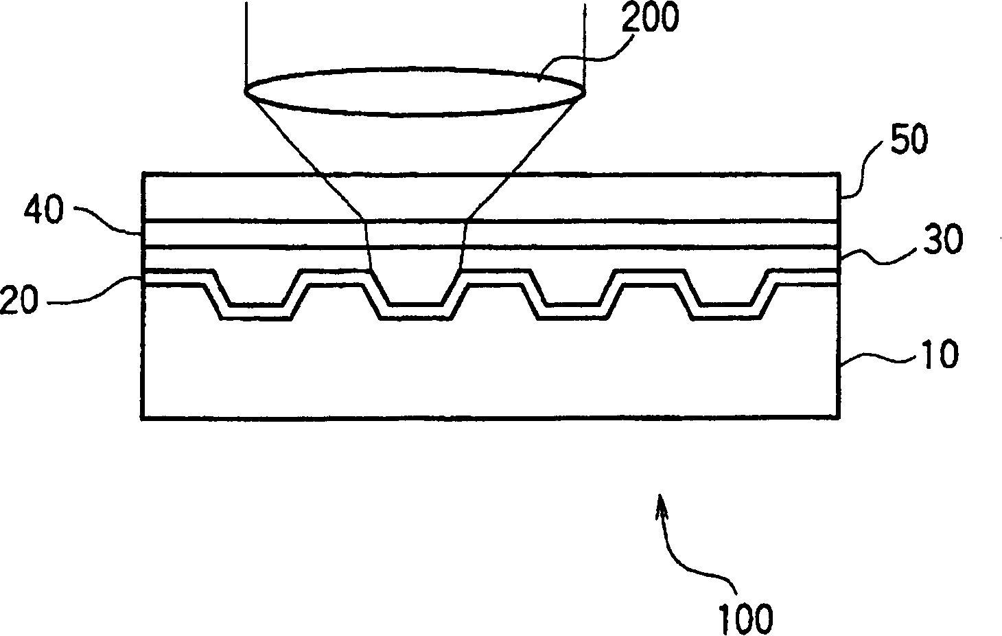
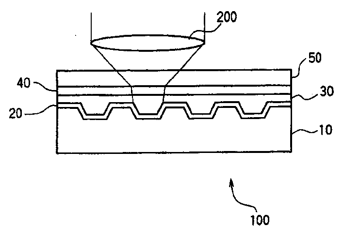
[0064] Injection molding polycarbonate resin (polycarbonate produced by Teijin Corporation, trade name: PanriteAD5503) substrate, which has a spiral groove (depth 100nm, width 0.120 μm, track pitch 0.3 μm), thickness 1.1 mm, diameter 120 mm. Ag was sputtered on the grooved surface of the obtained substrate to form a 100 nm thick light reflection layer.

[0065] Then, 2 g of phthalocyanine-based organic compound A (maximum absorption: 340 nm) was mixed in 148 ml of 2,2,3,3-tetrafluoropropanol, and subjected to ultrasonic treatment for 2 hours to dissolve it to prepare a coating for forming a recording layer. cloth liquid. Under the conditions of 23° C. and 50% RH, the prepared coating solution was applied on the light reflection layer by a spin coating method while cha...

Embodiment 2

[0073] In Example 1, the optical recording medium of Example 2 was produced in the same manner as in Example 1 except that the cyanine-based organic compound B (absorption wavelength: 373 nm) was used instead of the phthalocyanine-based organic compound A.

[0074] The same test as in Example 1 was carried out on the prepared optical recording medium to evaluate recording characteristics. The results are shown in Table 1. [Example 3]

Embodiment 3

[0075] In Example 1, the optical recording medium of Example 3 was produced in the same manner as in Example 1, except that the aminobutadiene-based organic compound C (absorption wavelength: 359 nm) was used instead of the phthalocyanine-based organic compound A.

[0076] The same test as in Example 1 was carried out on the prepared optical recording medium to evaluate recording characteristics. The results are shown in Table 1. [Example 4)


PUM

PropertyMeasurementUnit
thicknessaaaaaaaaaa
thicknessaaaaaaaaaa
thicknessaaaaaaaaaa

Abstract

An optical recording medium includes a substrate having successively disposed thereon a light-reflecting layer, a recording layer and a cover layer, with recording and playback being effected by irradiating the medium with a laser beam having a wavelength of 450 nm or less from the side disposed with the cover layer, wherein a sputter layer having a thickness of 1 to 80 nm is formed between the recording layer and the cover layer, and the sputter layer and the cover layer are adhered with an adhesive. So a high-density makeup recording type optical recording medium having superior recording characteristics is provided.

Description

technical field [0001] The present invention relates to a supplementary recording type optical recording medium having a recording layer made of an organic compound and capable of recording and reproducing with laser light of a specific wavelength. Background technique [0002] A supplementary recording type optical recording medium in which information can be recorded only once by laser light is widely known in the past and is called a CD-R. It is advantageous in that it can be reproduced by a commercially available CD player, and recently, the demand for it has increased along with the popularization of personal computers. In addition, as a medium capable of large-capacity recording by CD-R, a supplementary recording type digital versatile disc (DVD-R) for recording and the like in digital high-definition television has also been put into practical use. [0003] As a structure of these supplementary recording type optical recording media, it is known that on a disk-shaped...

Claims


Application Information

Patent Timeline
Patent Type & Authority Applications(China)
IPC IPC(8): B41M5/26G11B7/24G11B7/241G11B7/244G11B7/2542G11B7/2548G11B7/257G11B7/2578G11B7/26
CPCG11B7/2475G11B7/2578G11B7/245G11B7/2533G11B7/256G11B7/248G11B7/26G11B2007/25716G11B7/2542G11B2007/25713G11B2007/2571G11B7/2472G11B7/246G11B7/2478G11B7/2534G11B7/2531G11B7/2467Y10T428/21G11B7/259G11B2007/25715G11B7/24G11B7/2535G11B2007/25706G11B2007/25708
Inventor 齐藤真二角田毅石田寿男
Owner FUJIFILM CORP
Why Eureka
Eureka Blog
Learn More