Super-large size plastic injection moulding process and its equipment
An injection molding, super-large technology, applied in the field of super-large plastic injection molding technology and equipment, can solve the problems of long flow rate of the model, can not solve the problem of single injection point, etc., and achieve the effect of reducing the locking force, reducing the processing cost and reducing the pressure
- Summary
- Abstract
- Description
- Claims
- Application Information
AI Technical Summary
Problems solved by technology
Method used
Image
Examples
Embodiment 1
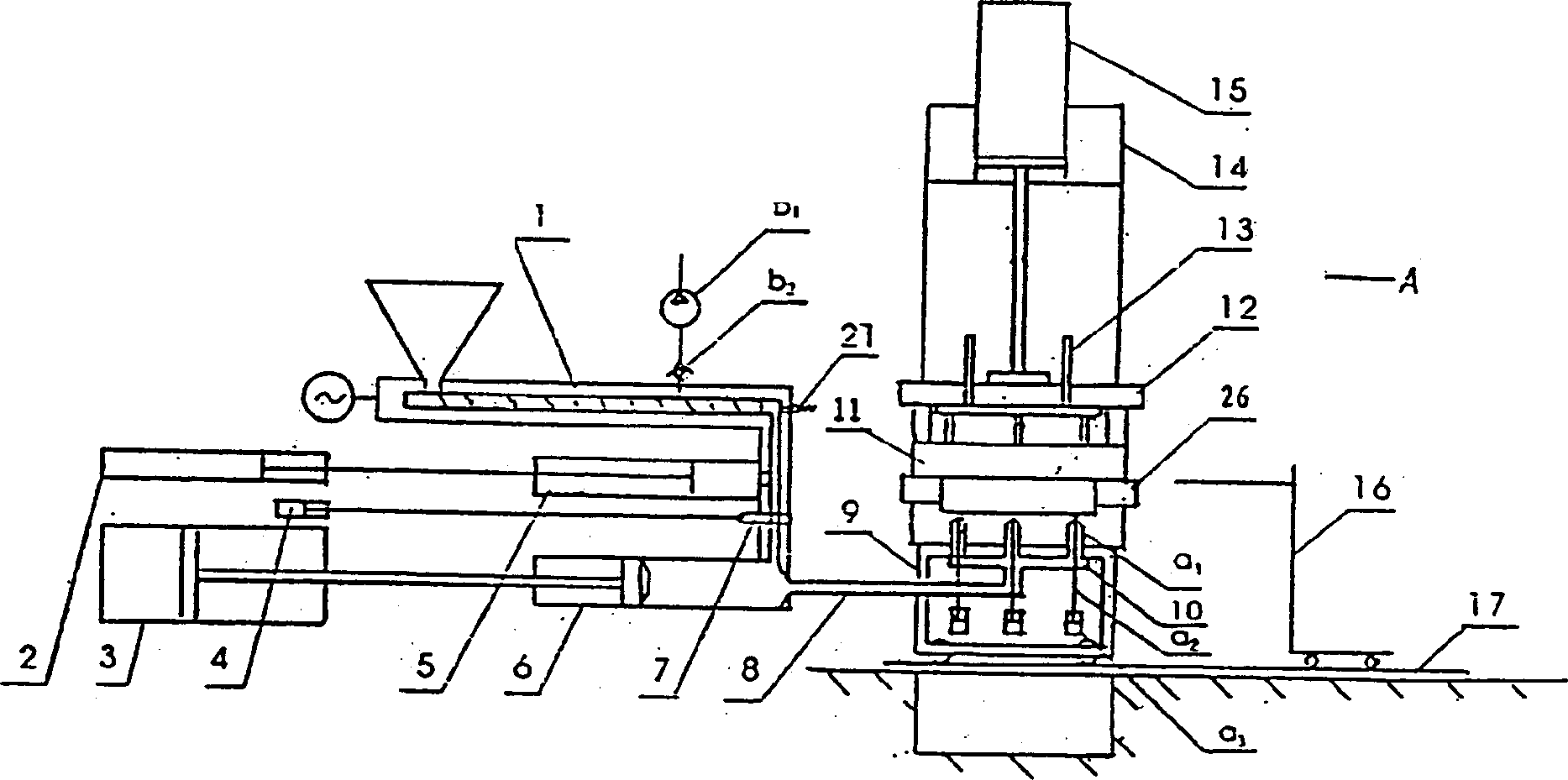
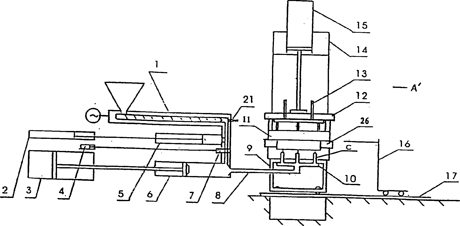
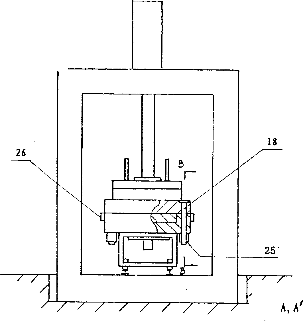
[0031] Embodiment 1, the equipment that is especially suitable for the ultra-large plastic injection molding process described in Embodiment 1, including storage injection molding, pre-molding mechanism 1, storage cylinder 2, injection cylinder 3, distributor cylinder 4, storage cylinder 5, injection cylinder 6 , Distributor 7, large manifold 8, hot runner 10, mold 11, movable template 12, reverse push rod 13, press 14, press cylinder 15, take out product car 16, guide rail 17 and hydraulic system; there is also a belt Toothed mold guide post 18, symmetrical toothed push plate 19, system safety discharge valve 21, backing plate 22, integral locking cylinder 20, piston 24, open nozzle a 1 , tappet a 2 , open nozzle cylinder a 3 , Ordinary solid nozzle is large, nitrogen booster pump b 1 and check valve b 2 .
Embodiment 2
[0032] Embodiment 2, ultra-large plastic injection molding process, on the basis of Embodiment 1, the necessary and sufficient conditions for automatic start are: the upper position of the movable template, the rear position of the lock block, the amount of material in the injection cylinder is in place, the closed position of the distributor, and the The product car is at the rear, the open nozzle is sealed by the tappet, and the nozzle oil cylinder is at the front; at this time, the molten material fully mixed with high-pressure nitrogen enters the storage cylinder 5, and the storage cylinder retreats freely.
Embodiment 3
[0033] Implementation 3. Super large plastic injection molding process. On the basis of Embodiment 1 or 2, the automatic process is: automatic start, the movable template is pressed down to close the mold, fast and slow, tooth-shaped push plate clamping, injection cylinder injection, injection Divided into three forms: injection I, injection II and pressure keeping. At the same time, the open nozzle tappet retreats and the nozzle is opened; after injection, the distributor opens, and the open nozzle tappet moves forward at the same time, sealing the nozzle and storing the cylinder. Push it to the front position and self-lock, the injection cylinder fast retreats, the molten material directly enters the injection cylinder, when the injection cylinder reaches the material volume, the distributor is closed, and the storage cylinder moves back freely; when the set cooling time is reached, the toothed push plate opens and moves The template rises and turns quickly at a slow speed; a...
PUM
 Abstract
Description
Claims
Application Information
 - R&D
- Intellectual Property
- Life Sciences
- Materials
- Tech Scout
- Unparalleled Data Quality
- Higher Quality Content
- 60% Fewer Hallucinations
Browse by: Latest US Patents, China's latest patents, Technical Efficacy Thesaurus, Application Domain, Technology Topic, Popular Technical Reports.
© 2025 PatSnap. All rights reserved.Legal|Privacy policy|Modern Slavery Act Transparency Statement|Sitemap|About US| Contact US: help@patsnap.com


