

Apex cuvature radius measuring method and device for aspherics
An aspherical mirror, vertex curvature technology, applied in measuring devices, optical devices, lenses, etc., can solve the problems of vertex curvature radius error, complex measurement system, slow measurement speed, etc., to achieve improved calculation accuracy, high measurement accuracy, easy to use. effect achieved
Inactive Publication Date: 2003-03-19
TSINGHUA UNIV
View PDF0 Cites 33 Cited by
- Summary
- Abstract
- Description
- Claims
- Application Information
AI Technical Summary
Problems solved by technology
The direct measurement method is a contact measurement, which can be realized by a three-coordinate machine or a ball-and-stick method, and the radius of curvature of the vertex can be obtained directly, but the measurement speed is slow and it is easy to scratch the surface; the light wave surface measurement method is a non-contact measurement, based on light waves Surface compensation interferometry (see: R.Diazuribe and M.Camposgarcia, Null-screen testing of fast convex aspheric surface, Appl.Opt.39 (16) 2670-2677, 2000) is widely used, the surface shape of aspheric surface The measurement accuracy is high, but the measurement of the vertex curvature radius is based on the surface shape data, which is calculated by the method of surface fitting, so the small error of the surface shape measurement will lead to a large vertex curvature radius error, especially when the curvature radius is larger When the value is large, the error is relatively large. In addition, the measurement system is relatively complicated, and it is difficult to realize online measurement during aspheric surface processing.
Method used
View moreImage
Smart ImageViewing Examples

Examples
Embodiment
[0034] Using the method and device of the present invention, adopting 4×4 dot matrix structured light, and applying it to the measurement of a paraboloid with a known vertex curvature radius, the following results are obtained.
[0035] Vertex curvature radius: 1300.0mm; average measurement error: <0.3%
Login to View More PUM
 Abstract
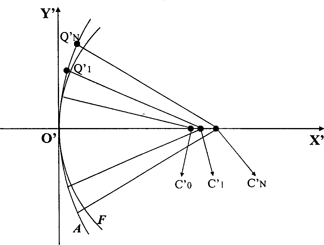
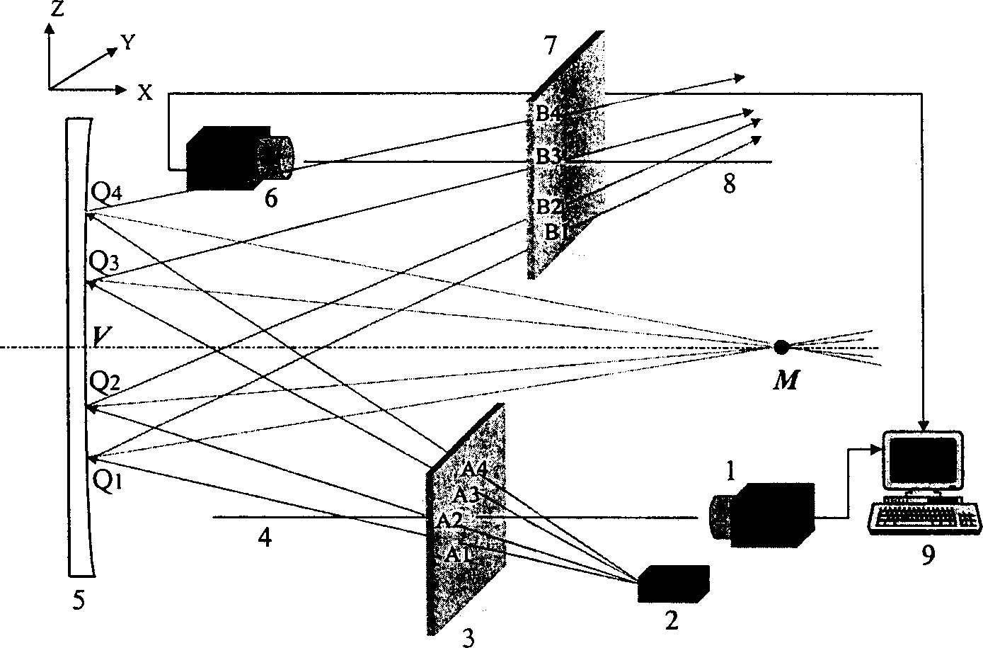
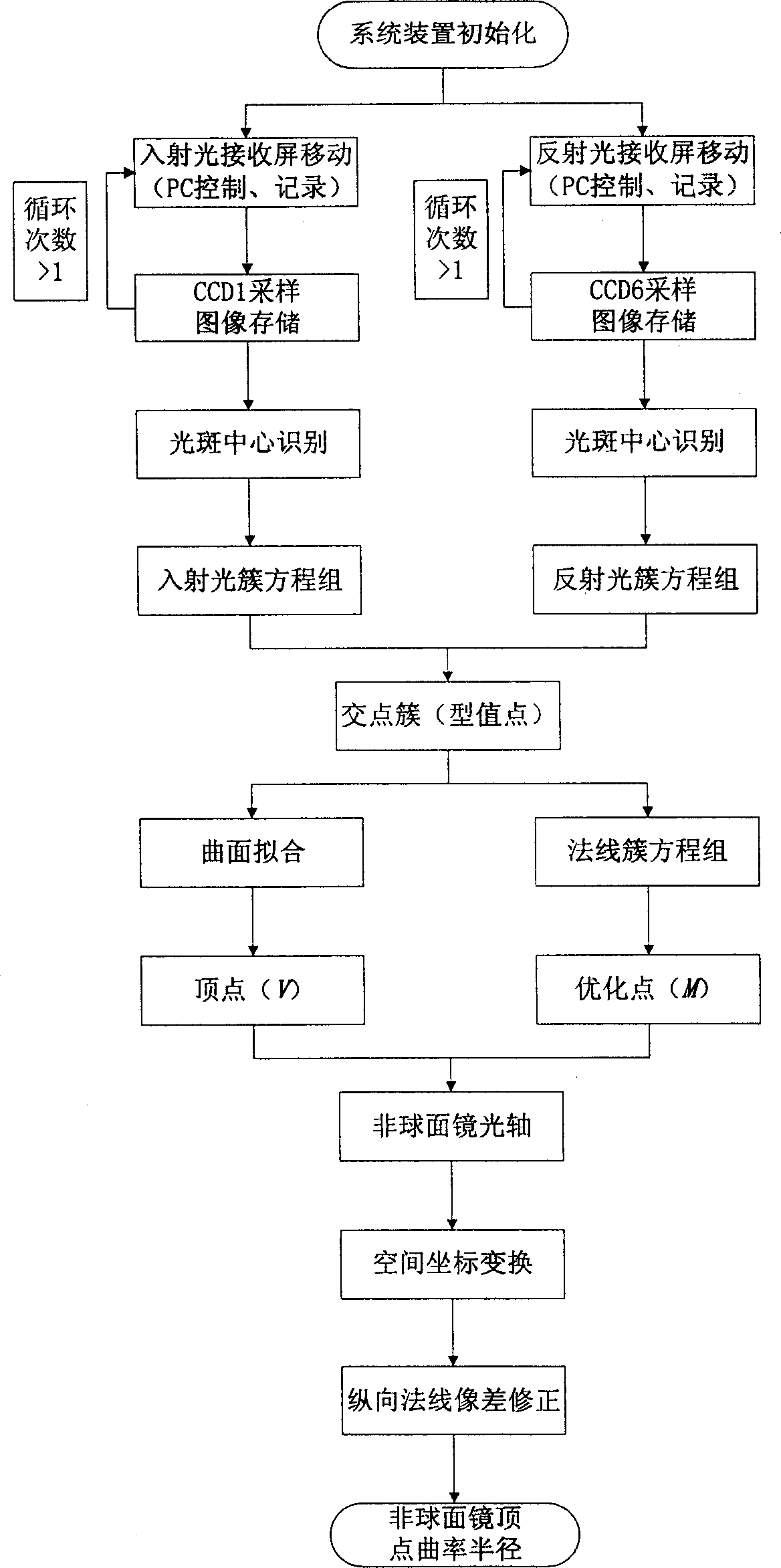
The present invention is one kind of apex curvature radius measuring method and device for aspherics and relates to the technology of measuring aspherical optical elements. Based on ray tracing principle, laser beam is projected to the measured aspherics in the dot array structural light mode, the positions of one incident light spot and the reflected light spot on light receiving screen are measured with a CCD camera, and the images of the incident flare and the reflected flare are analyzed and processed in computer, so that the apex curvature radius of the aspherics is obtained. The method has relatively high measurement precision, especially to large apex curvature radius of aspherics, and the present invention may also realize the in-situ measurement of the aspherics in its production.
Description
technical field [0001] The invention relates to a detection technology of an optical element, in particular to a method and device for directly measuring the radius of curvature of the vertex of an aspheric mirror, for example, used for direct measurement of the radius of curvature of the vertex of the aspheric mirror in the on-line detection of the production and processing of the aspheric mirror. Background technique [0002] Aspheric elements can effectively eliminate aberrations, improve the imaging quality of the optical system, and at the same time reduce the weight of the optical system, improve stability, and reduce costs. It has been recognized by optical workers and has been used in space optical systems and military applications. It has been widely used in optical systems, astronomy and high-tech civilian products. However, due to the high difficulty in manufacturing and testing of aspheric components for a long time, the traditional manual processing method has b...
Claims
Login to View More Application Information
Patent Timeline
 IPC IPC(8): G01B11/24G01B11/255G02B3/02G06T7/00
Inventor曾理江王浩殷纯永
OwnerTSINGHUA UNIV