Small mechanical variable laser strength attenuator

A light intensity attenuation, mechanical technology, applied in lasers, laser parts, optics, etc., can solve the problems of not very large adjustable range of light intensity attenuation, difficult to achieve mass production, complex film production process, etc. Wide working wavelength range, no transmission loss, low price

Inactive Publication Date: 2003-03-19
SHANGHAI JIAO TONG UNIV
View PDF1 Cites 9 Cited by
  • Summary
  • Abstract
  • Description
  • Claims
  • Application Information

AI Technical Summary

Problems solved by technology

There are following deficiencies in the method for realizing laser light intensity attenuation by adjusting the position of the attenuation film: 1. The film manufacturing process is complicated. In order to realize that the light intensity attenuation is different and changes continuously at different positions, the film thickness should also be continuously changed. It is difficult to control during the production process, and it is not easy to achieve mass production, which results in relatively high costs; 2. The adjustable range of light intensity attenuation is not very large; 3. Under the same working condition (the position where the beam passes through the film is the same), The light attenuation of different wavelengths is relatively different, so it is not easy to achieve uniformity when realizing the display of the attenuation

Method used


Image

  • Small mechanical variable laser strength attenuator
  • Small mechanical variable laser strength attenuator
  • Small mechanical variable laser strength attenuator

Examples


Embodiment 1

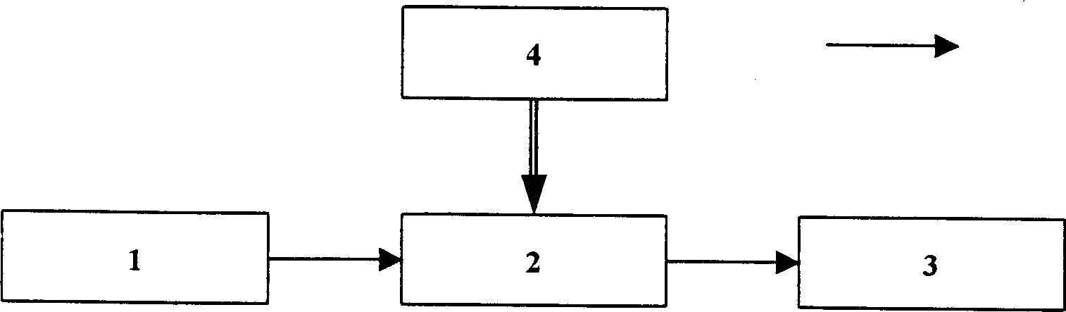
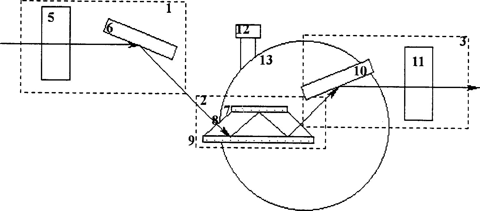
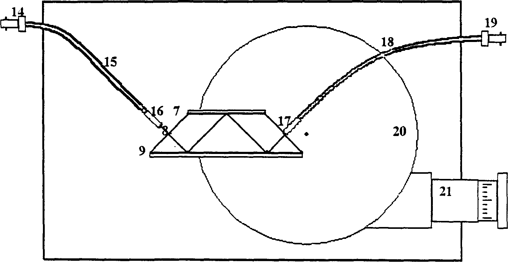
[0023] Embodiment 1: Taking the light intensity attenuator with optical fiber connector as an example, the optical input part is composed of optical fiber connector 14, optical fiber 15 and optical fiber self-focusing lens 16. The standard optical fiber connector 14 can be easily connected with the input light, such as a pigtailed fiber The output laser is connected in the form of optical fiber, and the self-focusing lens 16 keeps the light parallel, and the light is incident on the light intensity attenuation device 2 from the light input part 1 in a fixed direction.

[0024] The light intensity attenuation device 2 is composed of an isosceles trapezoidal prism 8, an upper dielectric film 7, and a lower dielectric film 9. The parameter design of the light intensity attenuation device 2 takes 1.3 μm as the center wavelength. If other wavelengths are selected as the working wavelength, the parameter design needs to be redesigned. optimization. In the light intensity attenuation...

Embodiment 2

[0027] Embodiment 2: Taking a large-aperture laser light intensity attenuator as an example, the light input part 2 is composed of an incident window 23 , a collecting lens 24 and a plane mirror 25 . The collecting lens 24 keeps the light rays parallel. The plane mirror 25 changes the direction of light propagation, so that the reflected output light and input light are kept in a straight line.

[0028]The light intensity attenuation device 2 is composed of an isosceles trapezoidal prism 8, an upper dielectric film 7, and a lower dielectric film 9. The parameter design of the light intensity attenuation device 2 takes 1.3 μm as the center wavelength. If other wavelengths are selected as the working wavelength, the parameter design needs to be redesigned. optimization. In the light intensity attenuation device 2, the prism 8 is an isosceles trapezoidal prism with high refractive index (ZF7, n=1.750, base angle 38.45°), and the upper and lower bottom dielectric films 7 and 9 us...


PUM


Abstract

The present invention is one kind of laser device. The small mechanical variable laser strength attenuator includes laser input unit; laser strength attenuating unit, laser output unit and control unit connected via optical path. Laser beam is projected via the laser input unit to the laser strength attenuating unit on the angle turning part of the control unit, its incident angle is regulated by the control unit, and the laser beam after being attenuated in the laser strength attenuating unit is output via the laser output unit. The present invention is used in optical communication, optical information processing and other fields needing laser strength attenuation as well as precise ranging, holographic information processing, etc.

Description

technical field [0001] The invention relates to a laser light intensity attenuation device, in particular to a small mechanical variable laser light intensity attenuation device, which belongs to the field of laser devices. Background technique [0002] Due to the high intensity and power of the laser itself, in some applications, it often exceeds the ability of the subsequent device to withstand the light intensity. Therefore, if the light intensity is not properly attenuated, it will inevitably cause damage to the subsequent device. A light intensity attenuator is a device inserted into an optical circuit. Its purpose is to artificially controllably attenuate the light intensity so that the output light meets the requirements in terms of intensity or power. After literature search, it is found that the U.S. patent application number is: 6130984, the application date is: 2000.10.10, and the invention name is: small adjustable light intensity attenuator. This patent introduc...

Claims


Application Information

Patent Timeline
Patent Type & Authority Applications(China)
IPC IPC(8): G02B6/34G02B26/02H01S3/00
Inventor 曹庄琪刘志强沈启舜陈洸袁文
Owner SHANGHAI JIAO TONG UNIV
Why Eureka
Try Eureka