Cascade superhigh temperature water source heat pump apparatus

A water source heat pump and ultra-high temperature technology, which is applied in heating devices, heat pumps, geothermal power generation, etc., can solve the problems of energy efficiency ratio of only about 1.5, water temperature that cannot meet the requirements, and high condensation pressure, so as to reduce pipeline specifications and pump energy delivery , Good water supply temperature and high water supply temperature

Inactive Publication Date: 2003-03-26
阎首弟 +2
View PDF0 Cites 4 Cited by
  • Summary
  • Abstract
  • Description
  • Claims
  • Application Information

AI Technical Summary

Problems solved by technology

[0004] However, the current water source heat pump heating has not yet reached the standard heating water supply temperature, and its maximum water supply temperature is 60°C, which is far from the minimum standard heating water temperature of 90°C
Moreover, the energy efficiency is relatively low at this time, and the normal working condition of water supply and return is around 50 / 40°C. If it is used in an air-conditioning fan coil cooling system, it can barely be used, but if it is used in a heating system, the water temperature will be low, especially when the old system is renovated. Since the original radiator is configured according to the standard water temperature of 70-90°C
Therefore, the water temperature around 50°C is usually difficult to meet the requirements.
[0005] Since the current water source heat pump devices use medium-temperature refrigerants (such as R 22 ) for stand-alone circulation, this device has a large compression ratio and high condensation pressure, so it is impossible to form a high water supply temperature, and simply use high-temperature refrigerant for stand-alone operation, and can only extract heat from a heat source above 40°C, otherwise The energy efficiency ratio is only about 1.5, so the goal cannot be achieved

Method used


Image

  • Cascade superhigh temperature water source heat pump apparatus
  • Cascade superhigh temperature water source heat pump apparatus
  • Cascade superhigh temperature water source heat pump apparatus

Examples


Embodiment Construction

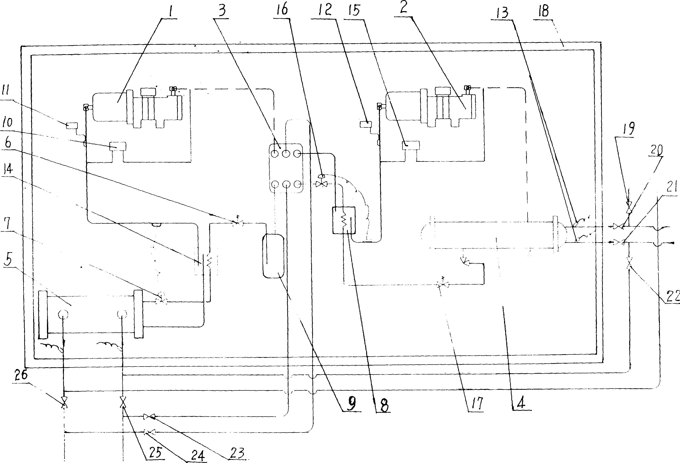
[0017] The present invention will now be described in further detail with reference to the drawings.

[0018] figure 1 This is a specific embodiment of the present invention: the device cabinet 18 is equipped with an evaporator 5, and the medium output port of the evaporator 5 is connected with the medium inlet of the low-temperature vapor-liquid heat exchanger 14 by a copper pipe. The medium outlet of the low-temperature vapor-liquid heat exchanger 14 is connected with the medium inlet of the low-temperature compressor 1 by a copper pipe. A temperature switch 11 is installed on the copper pipeline connecting the vapor-liquid heat exchanger 14 and the low-temperature compressor 1, and one end of the low-temperature high-low pressure controller 10 is also installed on this pipeline. The medium output port of the low-temperature compressor 1 is connected to the low-temperature medium input port of the evaporative condenser 3 by a copper pipe. The low-temperature medium output port ...


PUM


Abstract

Overlap super high temperature water source thermal pump comprises a low, high temperature compressor in a cabinet in which the medium outlet of evaporizer is connected with the medium inlet of the high temperature gas/liquid heat exchanger by a connecting pipe while its outlet is connected with the medium inlet of a high temperature compressor, the outlet of which is connected with the medium inlet of a condenser and the outlet of which is connected with the inlet of a high temperature electromagnetic valve, which outlet is connected with the inlet of a high temperature gas/liquid heat exchanger, the outlet of which is connected with the inlet of the high temperature expansion valve and its outlet is connected with the evaporizer, with the supplied water temperature by 70-90 deg.C..

Description

(1) Technical field [0001] The invention relates to a heating device, in particular to a cascade ultra-high temperature water source heat pump device that converts low-grade heat energy of groundwater into high-grade heat energy that can be directly used. (2) Technical background [0002] At present, in our country, the heating and heating of buildings, except for part of the central heating for thermal power plants, is almost all for the heating of scattered fuel boiler houses. These heating devices rely on the direct combustion of solid fuel coal or oil to obtain heat, which is not only inefficient, It causes energy waste, and the carbon dioxide gas and smoke produced by combustion cause serious pollution to the environment. With the global energy crisis and the increasing awareness of energy conservation and environmental protection, exploring energy-saving and environmentally-friendly heating devices has become a top priority. [0003] The emergence and development of water s...

Claims


Application Information

Patent Timeline
Patent Type & Authority Applications(China)
IPC IPC(8): F24J3/08F25B30/02
CPCY02E10/10
Inventor 阎首弟程世哲高亚民
Owner 阎首弟
Why Eureka
Try Eureka