
Metal halide lamp

A metal halide lamp and halide technology, applied in the field of light-emitting tubes, can solve the problems of large changes in lamp color temperature and decrease in beam maintenance rate, and achieve the effects of increasing lamp life, suppressing the decrease in beam maintenance rate, and improving lamp efficiency

Inactive Publication Date: 2003-04-02
PANASONIC CORP
View PDF2 Cites 3 Cited by
  • Summary
  • Abstract
  • Description
  • Claims
  • Application Information

AI Technical Summary

Problems solved by technology

[0005] However, in conventional metal halide lamps in which cerium iodide and sodium iodide are sealed as luminescent substances, there is a problem that the light beam maintenance rate decreases significantly with the lapse of the lighting time, and there is also a problem that the color temperature of the lamp changes greatly.

Method used


Image

  • Metal halide lamp
  • Metal halide lamp
  • Metal halide lamp

Examples


Embodiment 1

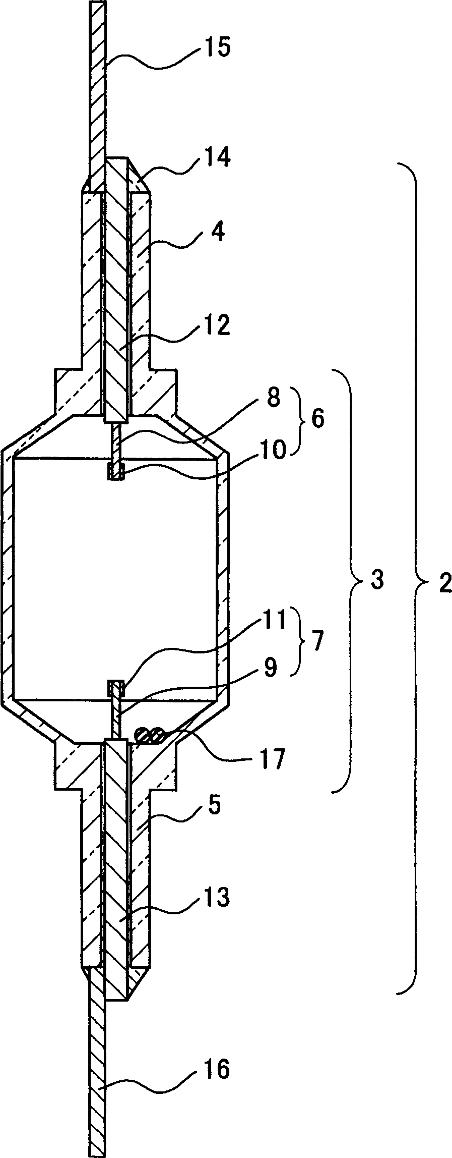
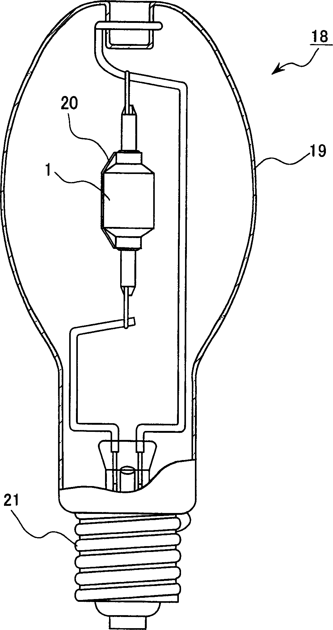
[0030] Preparation of CeI 3 : 2.4mg (40.0wt%), NaI: 3.15mg (52.5wt%), TlI: 0.27mg (4.5wt%), InI 0.18mg (3.0wt%) as the light-emitting substance 17, the lamp 18 was sealed, and its initial stage was measured. characteristics and beam maintenance in relation to aging.

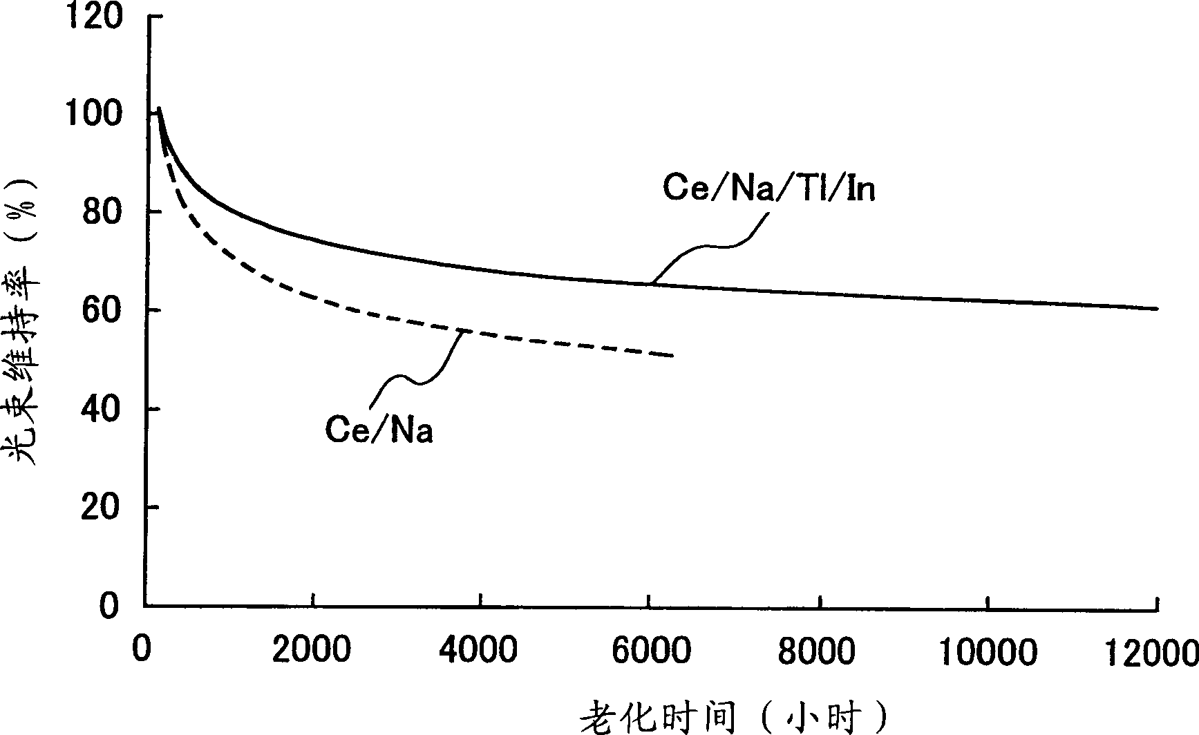
[0031] As a result, it was observed that basically the encapsulation of TlI and InI broadened the discharge arc and also suppressed the bending of the discharge arc to the upper side of the arc tube and the side of the arc tube. Furthermore, the lamp 18 of this embodiment has an improved luminous flux maintenance rate related to aging, and can achieve a rated life time of 12,000 hours with a luminous flux maintenance rate of 60% or more. Basically, it can be said that the average excitation voltage Ve of thallium Tl and indium In is higher than the ionization voltage Vi (Ve>0.585Vi), so that such a discharge arc broadening effect is obtained.

[0032] Furthermore, it was confirmed that the encapsulation of thal...

Embodiment 2

[0034] As in Example 1, as the luminescent substance 17, CeI 3 : 2.5mg and NaI: 3.0mg, and sealed relative to the total amount of metal halides, TlI and InI whose composition was changed in the range of 0-15wt%, respectively, to prepare lamp 18, and measure its initial characteristics and aging correlation beam maintenance rate.

[0035]As a result, it was observed that the discharge arc was broadened basically accompanying the encapsulation of TlI and InI, and the bending of the discharge arc toward the tube wall was also suppressed. Moreover, the aging-related beam maintenance rate of the lamp 18 of the present embodiment is improved. If the encapsulation of TlI and InI is within the range of 1.0≤TlIwt%≤7.0, and in the range of 0.6≤TlIwt% / InIwt%≤4.0, it can be achieved The rated life time is 12,000 hours with the beam maintenance rate above 60%. The result is shown in image 3 In the Ce / Na / Tl / In graph. This can be said to be basically because the average excitation volta...


PUM


Abstract

Provided is a metal halide lamp, comprising a luminous tube (3) whose outer shell is made of an oxide-based translucent ceramic material. In the luminous tube (3), cerium halides and sodium halides are combined and sealed as luminous substances. compounds, halides of thallium and halides of indium. With respect to all metal halides, it is preferable that the halide of cerium is more than 20wt% and less than 69.0wt%, the halide of sodium is more than 30wt% and less than 79.0wt%, and the total amount of halide of thallium and halide of indium is 1.0 More than wt% and less than 20 wt%. As a result, the discharge arc is broadened, the bending toward the wall of the luminous tube is suppressed, and the lamp efficiency is improved. Even if it is used for a long time, the reduction of the beam maintenance rate can be suppressed, and the hue of the luminous color can be compensated.

Description

technical field [0001] The invention relates to a luminescent tube of a metal halide lamp. Background technique [0002] Recently, metal halide lamps using ceramic luminous tubes have higher efficiency, higher color rendering, and longer life than metal halide lamps using quartz luminous tubes, so they are mainly used as indoor lighting in shops and the like. universal. [0003] Figure 5 , Figure 6 They are the structures of conventional metal halide lamps using ceramic luminous tubes. As the structure of the arc tube 28, the arc tube container 29 is composed of a discharge arc tube portion 30 made of a polycrystalline alumina ceramic material and a pair of thin tube portions 31, 32 sintered at both ends thereof. A pair of tungsten coil electrodes 33 and 34 are provided at both ends of the arc tube 28 . In addition, power supply bodies 35, 36 made of niobium or conductive cermets are hermetically sealed in the light-emitting tube thin tube parts 31, 32 through glass fr...

Claims


Application Information

Patent Timeline
IPC IPC(8): H01J61/20C04B35/00H01J1/02H01J7/24H01J61/12H01J61/30H01J61/44H01J61/52H01J61/54H01J61/82H01K1/58
CPCH01J61/125H01J61/302
Inventor 东昌范西浦义晴织田重史柿坂俊介榎并博司
Owner PANASONIC CORP
Learn More