
Reversible circulation two phase biological nitrogen and phosphorus eliminating technology

A biological denitrification and double-cycle technology, applied in the field of nitrogen and phosphorus, can solve the problems of increased difficulty in operation control, poor operation stability, and low treatment efficiency, and achieve improved volume utilization, phosphorus removal rate, Reduce the effect of distractions and restrictions

Inactive Publication Date: 2003-04-16
黄勇 +1
View PDF0 Cites 23 Cited by
  • Summary
  • Abstract
  • Description
  • Claims
  • Application Information

AI Technical Summary

Problems solved by technology

This makes these processes inherently more complex
[0004] In order to overcome the problems that various processing functions are highly correlated due to the mixed culture of multiple populations, thereby increasing the difficulty of operation control, resulting in low processing efficiency and poor operation stability, the present invention provides a sludge phase-separated culture, suspension growth A new biological denitrification and phosphorus removal process combined with attachment growth, sequencing batch and continuous flow——bicycle two-phase (BICT) biological nitrogen and phosphorus removal process

Method used


Image

  • Reversible circulation two phase biological nitrogen and phosphorus eliminating technology
  • Reversible circulation two phase biological nitrogen and phosphorus eliminating technology
  • Reversible circulation two phase biological nitrogen and phosphorus eliminating technology

Examples


Embodiment 1

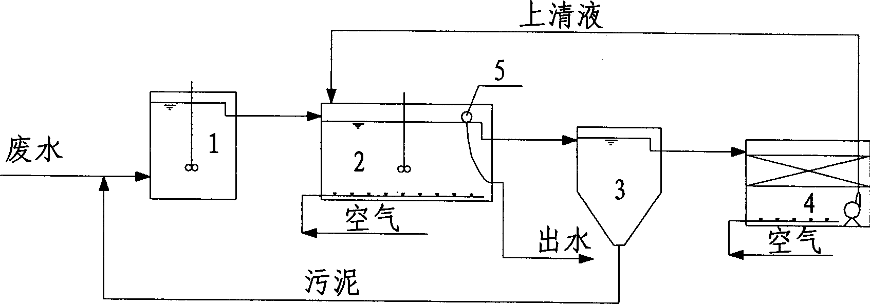
[0036] Embodiment one: see attached figure 1 As shown, an overall intermittent flow double-cycle two-phase biological denitrification and phosphorus removal process consists of a pre-anaerobic reactor 1, a suspension growth main reactor 2 operated in sequence batch mode, a sedimentation tank 3 and a biofilm reactor 4. Four main units are formed spatially, and the sedimentation tank 3 is arranged between the main reactor 2 and the biofilm reactor 4 .

[0037] exist figure 1 In the process, the waste water entering the system enters the pre-anaerobic reactor 1 together with the return sludge of the sedimentation tank 3, and stirs and reacts without oxygen supply, while entering and exiting; the mixed liquid flowing out of the anaerobic reactor 1 Entering the sequence batch main reactor 2, the four unit operations of water inlet / aeration, anoxic stirring, static sedimentation, water skimming / idle are completed sequentially, respectively to realize the degradation of organic matt...

Embodiment 2

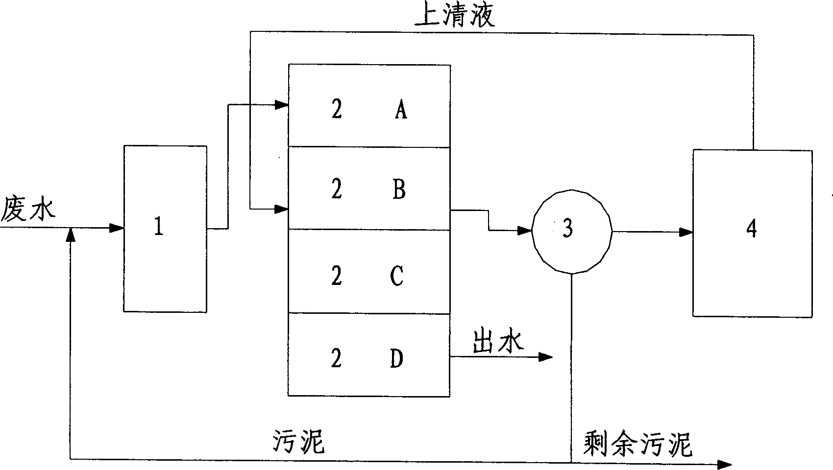
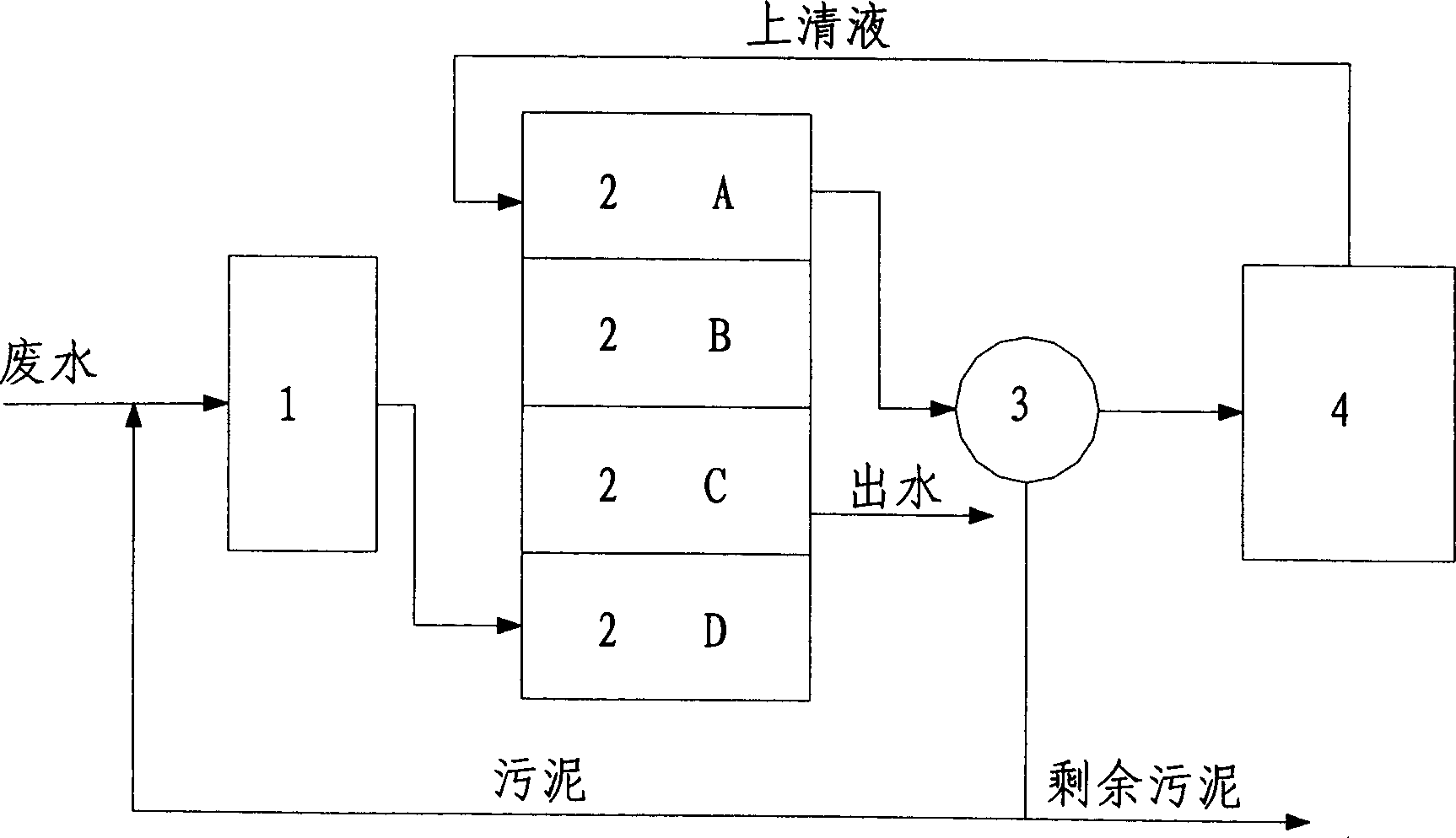
[0038] Embodiment two: see attached Figure 1 to Figure 5 As shown, an integral continuous flow partial intermittent double-cycle two-phase biological nitrogen and phosphorus removal process. The difference from Example 1 is that the main reactor is composed of 4 biological reaction pools A, B, C, and D that are independent of each other and operate in sequence batch mode. In this system, the anaerobic reactor 1 and the biofilm nitrification reactor 4 are always operated in a continuous flow mode, but according to the operation status of each reaction tank in the sequencing batch main reactor 2, the mixed liquid and nitrification liquid are sent to into the corresponding reaction pool. The sedimentation tank 3 also works in a continuous flow mode, sequentially receiving the mixed liquid from different reaction tanks, and sending the clarified effluent and return sludge to the biofilm nitrification reactor 4 and anaerobic reactor 1 respectively. . The four reaction tanks A, ...


PUM


Abstract

A process for denitrification and removing phosphorus from sewage features use of an preposed anaerobic reactor for mixing the sewage with the reflux sludge from a deposition pool, a primary reactor for culturing the heterotrophic microbes including phosphorus-gathering bacteria and denitrofying bacteria, removing COD, denitrofying and removing phosphorus, a deposition pool for separating mud andwater and draining the supernatant, and a biomembrane reactor for culturing the nitrosating and nitrofying bacteria for nitrofying the said incoming supernatant and returning it back to the said primary reactor.

Description

technical field [0001] The invention relates to the technical field of wastewater biological treatment, in particular to removing organic pollutants, especially nitrogen and phosphorus, from wastewater. Background technique [0002] Among wastewater treatment technologies, biological treatment is generally accepted as a cost-effective technology for nitrogen and phosphorus removal. The current biological nitrogen and phosphorus removal processes can be roughly divided into two categories: continuous flow and sequencing batch. The continuous flow process provides alternate anaerobic, anoxic and aerobic environmental conditions and multiple reflux measures in space to meet the process conditions of nitrogen and phosphorus removal. Typical continuous flow nitrogen and phosphorus removal technologies are A / A / O, Bardenpho, UCT, Phoredox and other treatment processes. The Sequential Batch (SBR) activated sludge process uses a variety of control methods t...

Claims


Application Information

Patent Timeline
IPC IPC(8): C02F3/00C02F3/28
Inventor 黄勇李勇
Owner 黄勇
Learn More