
Composite Circulation fluidized dry desulfurization process for flue gas and desalfurizing reaction tower

A technology of dry flue gas desulfurization and combined cycle, which is applied in the direction of chemical instruments and methods, separation methods, and separation of dispersed particles, which can solve the problems of reducing the effective space utilization rate of the reaction tower, poor surface activity of desulfurizing agent particles, and clean flue gas carryover. Problems such as excessive water volume, to achieve the effect of improving space utilization, prolonging space and time, and reducing water consumption requirements

Inactive Publication Date: 2003-06-25
WUHAN KAIDI ELECTRIC POWER CO LTD
View PDF3 Cites 19 Cited by
  • Summary
  • Abstract
  • Description
  • Claims
  • Application Information

AI Technical Summary

Problems solved by technology

Due to the narrow temperature range of the desulfurization reaction, the desulfurization reaction towers of these two technologies use water spraying to reduce the temperature of the flue gas to an appropriate range
At the same time, due to the installation of the internal separation device (the same facility is also used in the patent CN1195573), the smoke resistance is increased and it is easy to cause corrosion
[0007] It can be seen from the above that all the above-mentioned dry desulfurization technologies have various problems, such as a large amount of water carried by the clean flue gas, or a complex digestive system, or poor surface activity of desulfurizer particles, or large resistance, easy to Corrosion, blockage, etc. At the same time, because the flue gas inlet temperature is generally greater than 120 ° C, only water spraying in the tower is used to cool down, which reduces the utilization rate of the effective space of the reaction tower
Moreover, all technologies do not take into account the influence of factors such as the fluidized bed reaction system not being fluidized due to changes in the load of the combustion equipment and the reduction of the flue gas volume, and the load regulation is poor.

Method used

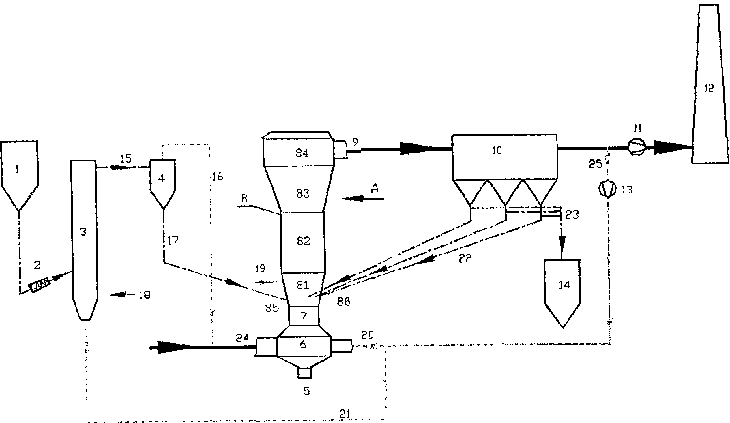
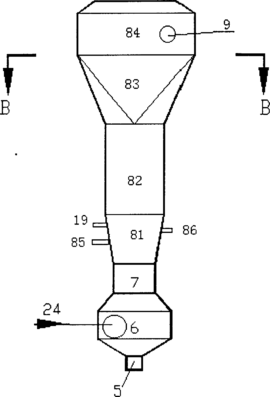
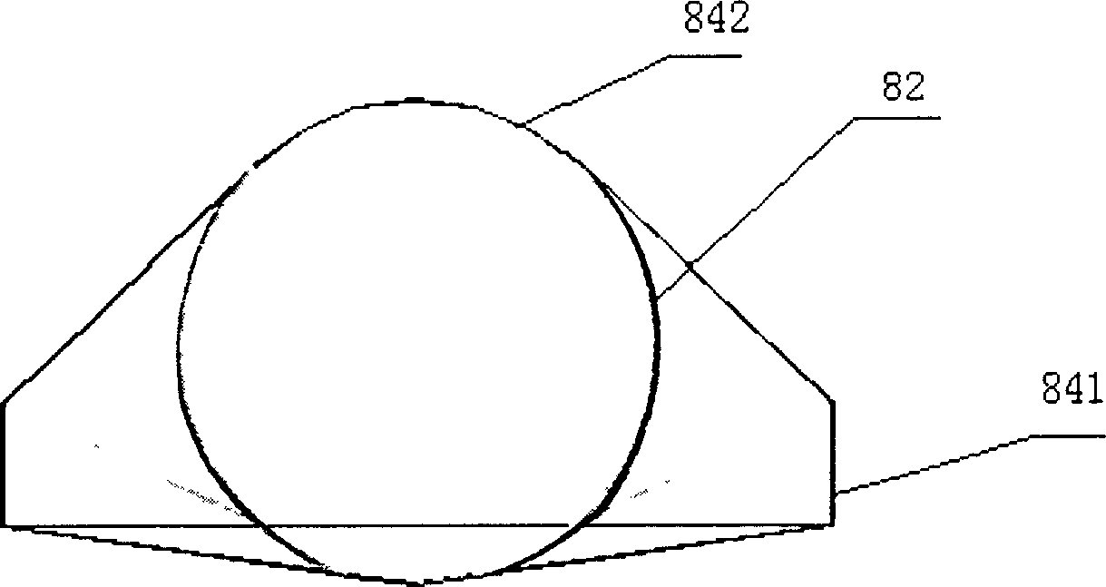

Image

  • Composite Circulation fluidized dry desulfurization process for flue gas and desalfurizing reaction tower
  • Composite Circulation fluidized dry desulfurization process for flue gas and desalfurizing reaction tower
  • Composite Circulation fluidized dry desulfurization process for flue gas and desalfurizing reaction tower

Examples


Embodiment Construction

[0026] First, the present invention simultaneously adopts three recycling methods to form a composite circulating fluidized desulfurization system:

[0027]1) Recirculation technology of desulfurizer particles in the desulfurization reaction tower is adopted.

[0028] This technology strengthens the internal circulation characteristics of the particles in the desulfurization reaction tower 8. Through a variety of layout and variable cross-section desulfurization tower design, the flow rate of flue gas in the tower changes step by step along with its rising process. On the one hand, it can reduce and adjust the particle drag force at the top of the absorption tower, and on the other hand, on the inner wall of the tower A local vortex zone is formed at the mutation point, which strengthens the internal circulation of the desulfurizing agent particles in the tower, and the internal circulation of the particles can reach between 40% and 80%. In the case of reducing the abrasion of the...


PUM


Abstract

The present invention features that line as desulfurizer material is made to pass through one clean wet fume slaking equipment to form slaked lime desulfurizer with high surface activity. In the system, there are three kinds of circulation modes, including inner circulation of desulfurizer grains; outer circulation and circulation of clean wet fume. The present invention is superior to available technology in that desulfurizing efficiency up to 90-92 % may be reached at relatively low Ca / S ratio, 1.1-1.3; that wide regulation ratio characteristic can meet the high efficiency desulfurizing requirement in load of the combustion equipment from 20% to 110%, and that the present invention has low water consumption and low cost.

Description

Technical field [0001] The invention relates to a composite circulating fluidized dry flue gas desulfurization process and a desulfurization reaction tower, belonging to the technical field of flue gas desulfurization, and particularly relates to a dry desulfurization system and process in flue gas discharged from various combustion equipment. Background technique [0002] The control of sulfur dioxide gas pollution has always been the focus of environmental protection in most countries in the world, and the pollutants produced by it are the largest source of pollution that causes damage to the ecological environment in our country. It has become a top priority for air pollution control in my country. [0003] At present, for the treatment of sulfur dioxide, the wet lime gypsum method (W-FGD) is generally adopted in foreign countries. Although the above method is adopted, although the removal effect is better, it has huge investment, large water consumption, large area, complex s...

Claims


Application Information

Patent Timeline
IPC IPC(8): B01D53/83
Inventor 张泽韩洪
Owner WUHAN KAIDI ELECTRIC POWER CO LTD
Learn More