
Temperature measurement node point suspension thin film electric thermocouple

A technology of thermocouple and thin film, applied in thermoelectric devices, measuring heat, circuits, etc., can solve the problems of fluid motion interference, reduce the heat capacity of junctions, and reduce the response speed of thermocouples to temperature changes, etc., so as to improve the response rate and reduce the The effect of thermal inertia

Inactive Publication Date: 2003-12-31
TECHNICAL INST OF PHYSICS & CHEMISTRY - CHINESE ACAD OF SCI
View PDF1 Cites 12 Cited by
  • Summary
  • Abstract
  • Description
  • Claims
  • Application Information

AI Technical Summary

Problems solved by technology

However, if it is used to measure the temperature of a liquid or gas, since the base material to which the film is attached usually has a much larger thickness, mass and heat capacity than the film element itself, the response speed of the thermocouple to temperature changes is significantly reduced, and may even be lower. For some filament type thermocouples
In addition, when the larger substrate is inserted into the fluid, it will interfere with the movement of the fluid, affecting the temperature field and measurement accuracy of the fluid
For overcoming this defect, U.S. Patent (RISGIN O., Method of Fabricating Film-Type Sensing Structures, USPatent #3715288, the manufacturing method of film-like sensing structure, 1973) adopts aluminum oxide film as the substrate of thermocouple film, for Thermal radiation sensor, which can reduce the thermal capacity of the junction, but still needs to be supported by the substrate

Method used


Image

  • Temperature measurement node point suspension thin film electric thermocouple
  • Temperature measurement node point suspension thin film electric thermocouple
  • Temperature measurement node point suspension thin film electric thermocouple

Examples


Embodiment 1

[0021] Example 1: Figure 3-1 To Fig. 3-5 is the schematic diagram of the manufacturing process of the present invention;

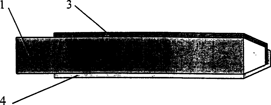
[0022] Such as Figure 3-1 As shown: the permanent substrate 1 is used as the structural basis of the thin-film thermocouple with the temperature-measuring node suspended in this embodiment, so that the thermocouple thin-film is attached to it, and lead contacts are provided;

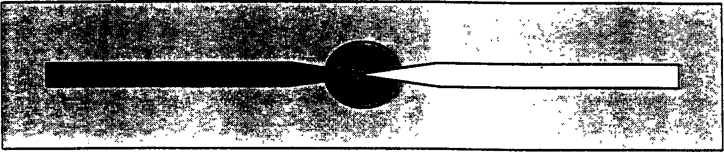
[0023] Figure 3-2 Shown: a non-permanent substrate 2 of smaller size is attached at the end or other specific location on the permanent substrate 1;

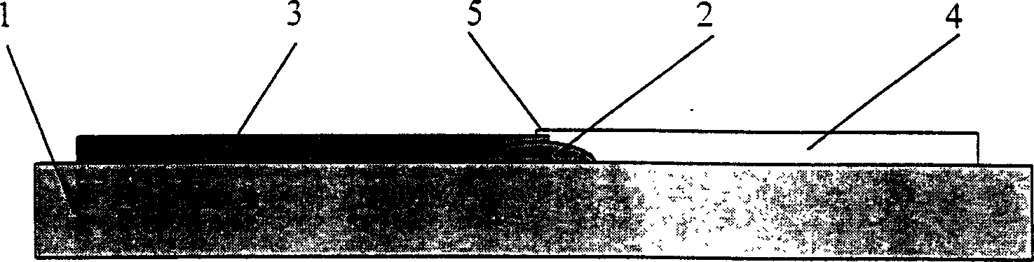
[0024] As shown in Figure 3-3: two kinds of thermocouple films 3 and 4 that constitute the film thermocouple suspended at the temperature measuring node are plated on the surface of the permanent substrate 1 respectively, and the intersection where the two thermocouple films overlap is is the temperature measuring junction 5 of the thermocouple;

[0025] Figure 3-43-3 is a view rotated 90° along its axis (i.e. the length direc...

Embodiment 2

[0028] Thin film thermocouple provided by the present invention can have multiple forms, diagram 2-1 Another embodiment given is a suspended thin-film thermocouple whose base is a flat plate type, Figure 2-2 For the top view before removal of the non-permanent substrate 2, Figure 2-3 After removal of the non-permanent substrate 2, the node is in a suspended state.

[0029] Its production process is:

[0030] 1. A non-permanent base 2 with a small size is attached to the middle of the flat permanent base 1,

[0031] 2. On the flat-type permanent substrate 1, the non-permanent substrate 2 is used as the overlapping point to coat the thermocouple film 3 and the thermocouple film 4 on both ends respectively, and the thermocouple film 3 and the thermocouple film 4 are placed on the non-permanent overlap on base 2;

[0032] 3. The non-permanent substrate 2 is removed, that is, the fabrication of the thin-film thermocouple with the temperature measuring node 5 suspended in thi...

Embodiment 3

[0034] The production process of this embodiment is:

[0035] 1. Punch a hole in the middle of the permanent substrate 1 in the shape of a flat sheet, thin tube or thin rod, and attach a non-permanent substrate 2 in the hole;

[0036] 2. On the permanent substrate 1, use the non-permanent substrate 2 attached in the hole as the overlapping point to coat the thermocouple film 3 and the thermocouple film 4 on both ends respectively, and the thermocouple film 3 and the thermocouple film 4 are in the non-permanent overlay on base 2;

[0037] 3. Remove the non-permanent substrate 2 attached to the hole, that is, complete the fabrication of the thin-film thermocouple with the temperature measuring node suspended in this embodiment.


PUM

PropertyMeasurementUnit
Thicknessaaaaaaaaaa

Abstract

The film thermocouple with suspended thermometric node includes permanent base of insulating solid material, and two layers of thermocouple film painted onto the surface of the permanent base. The superposed thermometric node of the two layers of thermocouple film is suspended without contact with the permanent base. The permanent base is made of ceramic, silicon chip, glass or organic polymer; and is in the shape of sheet, fine pipe or fine rod. The thermocouple film in the thickness of 1 nm to 0.1 mm is made of paired metal materials, PtRh-Pt, NiCr-constantan, semiconductor or metal oxide. Owing to the suspension structure of the thermometric node structure, the film thermocouple of the present invention has less heat inertia and thus high temperature change response rate.

Description

technical field [0001] The invention belongs to the field of engineering thermophysics and measuring instruments, in particular to a thin-film thermocouple with suspended temperature-measuring nodes. Background technique [0002] The measurement of temperature is to use the corresponding relationship between a certain characteristic of a substance or structure and its temperature, and convert the change of temperature into a change of a certain physical quantity corresponding to the temperature of the substance or structure, and this physical quantity can be directly measured. or displayed. [0003] A common mercury thermometer uses the volume change of mercury in a closed glass bulb as the temperature rises and falls (expressed as a change in the position of the mercury column in a glass capillary) to indicate the temperature; resistance thermometers use certain conductive substances such as The resistance value of platinum or copper changes wit...

Claims


Application Information

Patent Timeline
IPC IPC(8): G01K7/02H01L35/00
Inventor 周一欣刘静
Owner TECHNICAL INST OF PHYSICS & CHEMISTRY - CHINESE ACAD OF SCI
Features
  • Generate Ideas
  • Intellectual Property
  • Life Sciences
  • Materials
  • Tech Scout
  • Unparalleled Data Quality
  • Higher Quality Content
  • 60% Fewer Hallucinations
Learn More