Air exhaust pwrifying filter catalyst

A filter and catalyst technology, applied in the direction of physical/chemical process catalysts, catalyst carriers, filtration and separation, etc., can solve the problems of DPF damage, etc., and achieve the effects of improved oxidation activity, increased contact area, and excellent temperature rise

Inactive Publication Date: 2004-02-11
TOYOTA JIDOSHA KK
View PDF3 Cites 26 Cited by
  • Summary
  • Abstract
  • Description
  • Claims
  • Application Information

AI Technical Summary

Problems solved by technology

However, in this case, the greater the accumulation of PM, the higher the temperature during combustion, and the DPF may be damaged due to the thermal stress generated by it.

Method used


Image

  • Air exhaust pwrifying filter catalyst
  • Air exhaust pwrifying filter catalyst
  • Air exhaust pwrifying filter catalyst

Examples


Embodiment 1

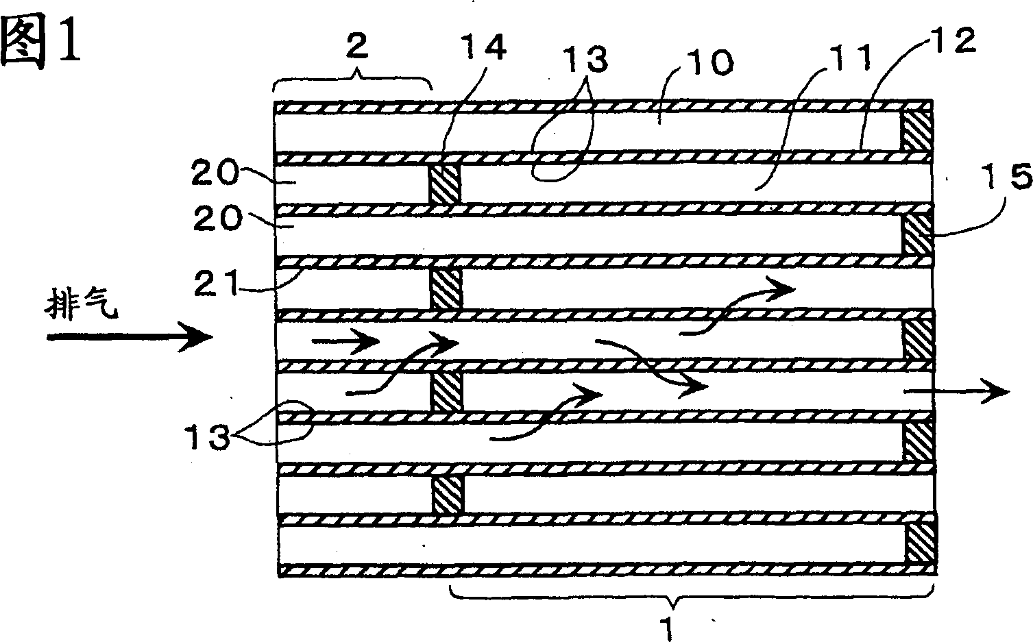
[0055] FIG. 1 is a cross-sectional view showing a main part of the exhaust gas purification filter catalyst of this embodiment. This exhaust purification filter catalyst includes a wall flow honeycomb structure portion 1 and an upstream side direct current honeycomb structure portion 2 integrally formed with the exhaust gas upstream side of the wall flow honeycomb structure portion 1 .

[0056] The wall-flow honeycomb structure part 1 includes an inflow-side cell 10 blocked on the exhaust gas downstream side, an outflow-side cell 11 adjacent to the inflow-side cell 10 and blocked on the exhaust gas upstream side, separating the inflow-side cell 10 and the outflow cell. The filter partition wall 12 of the side compartment 11 and the catalyst layer 13 formed on the surface of the filter partition wall 12 . In addition, the upstream straight-flow honeycomb structure part 2 includes the upstream straight cells 20 , the upstream cell partition walls 21 for partitioning the upstream...

Embodiment 2

[0064] Except that on the catalyst layer 13 of the upstream straight-flow honeycomb structure portion 2, 5 g of Pt was loaded per 1 liter volume of the upstream straight-flow honeycomb structure portion 2, but Li, Ba, and K were not loaded, the same as in Example 1. composition.

[0065] In this example, the oxidation activity in the upstream side direct flow honeycomb structure portion 2 was greatly improved compared with Example 1. Thus, the heat retention property of the intermediate plug 14 and the temperature rise property of the wall flow honeycomb structure portion 1 are further improved. (Example 3)

Embodiment 3

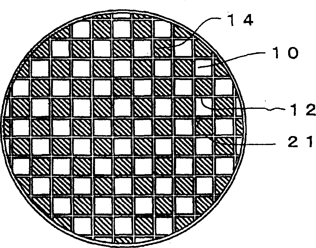
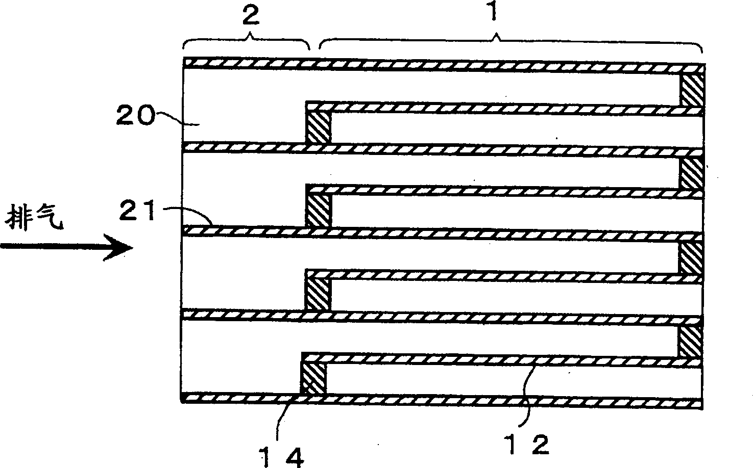
[0066] figure 2 A front view showing the inflow-side end face of the exhaust purification filter catalyst of this embodiment, image 3 A sectional view showing its main parts. This exhaust purification filter catalyst has the same configuration as that of the first embodiment except that every other upstream compartment partition wall 21 is cut to the position of the intermediate plug 14 .

[0067] In this embodiment, the temperature-rising exhaust gas easily comes into contact with the surface of the intermediate plug 14 by the reaction in the upstream-side straight-flow honeycomb structure portion 2, and since the upstream-side opening of the intermediate plug 14 becomes larger, it is difficult to further cause PM to The surface of the intermediate plug 14 builds up. Thus, clogging of the upstream straight compartment 20 can be further suppressed.

[0068] In this embodiment, the intermediate plug 14 is formed in the same manner as in the first embodiment, but the interme...


PUM

PropertyMeasurementUnit
pore sizeaaaaaaaaaa
lengthaaaaaaaaaa
lengthaaaaaaaaaa

Abstract

To suppress the piling of PM to an end face at the flow side of a DPF, and improve the purifying activity of PM. A straight flow honeycomb structure 2 at an upstream side is integrally formed at the exhaust gas upstream side of a wall flow honeycomb structure having a catalyst layer 13. PM is suppressed to be piled because an opening area of exhaust gas flow-in side end face is great. Thermal conductivity is improved and exhaust gas heat is smoothly conducted to the wall flow honeycomb structure 1 so as to raise the wall flow honeycomb structure 1 early and improve the activity of the catalyst layer 13.

Description

technical field [0001] The present invention relates to an exhaust gas purification filter catalyst for purifying exhaust gas containing particulates, such as exhaust gas from a diesel engine. Background technique [0002] For gasoline engines, harmful components in the exhaust gas have indeed been reduced due to strict regulations on exhaust gas and advances in technology capable of coping with the regulations. However, for diesel engines, due to the specific fact that harmful components are discharged in the form of particulates (particulate matter: carbon particles, sulfur particles such as sulfates, high-molecular-weight hydrocarbon particles, etc., hereinafter referred to as PM), regulations and technological progress are different from those of gasoline engines. slower than average. [0003] Exhaust purification devices for diesel engines that have been developed so far are known to be roughly classified into trapping exhaust purification devices (wall-flow) and open ...

Claims


Application Information

Patent Timeline
Patent Type & Authority Applications(China)
IPC IPC(8): F01N3/02B01D39/14B01D53/94B01J35/04F01N3/022F01N3/035F01N3/08F01N3/10F01N3/28
CPCB01J35/04F01N2330/38F01N3/0842F01N3/0821F01N3/0814F01N3/0222F01N3/035F01N2330/48F01N2240/20F01N3/021
Inventor 大河原诚治西村养石原干男
Owner TOYOTA JIDOSHA KK
Why Eureka
Try Eureka