Wave division complex mm wave light source row and corresponding optical fiber transmission radio signal communiation sysem

A wavelength division multiplexing and communication system technology, which is applied in the field of wavelength division multiplexing millimeter wave light sources, can solve the problems of poor performance of millimeter wave light sources, inability to share resources, high system costs, etc., and achieve cost reduction and cost reduction , high performance effect

Inactive Publication Date: 2004-03-03
PEKING UNIV
View PDF0 Cites 8 Cited by
  • Summary
  • Abstract
  • Description
  • Claims
  • Application Information

AI Technical Summary

Problems solved by technology

Each light source is relatively independent, and resources cannot be shared, which makes the cost of the system very high
When the RF frequency is mmWave frequency, the use of mmWave mixers and mmWave EO mo

Method used


Image

  • Wave division complex mm wave light source row and corresponding optical fiber transmission radio signal communiation sysem
  • Wave division complex mm wave light source row and corresponding optical fiber transmission radio signal communiation sysem
  • Wave division complex mm wave light source row and corresponding optical fiber transmission radio signal communiation sysem

Examples


Embodiment 1

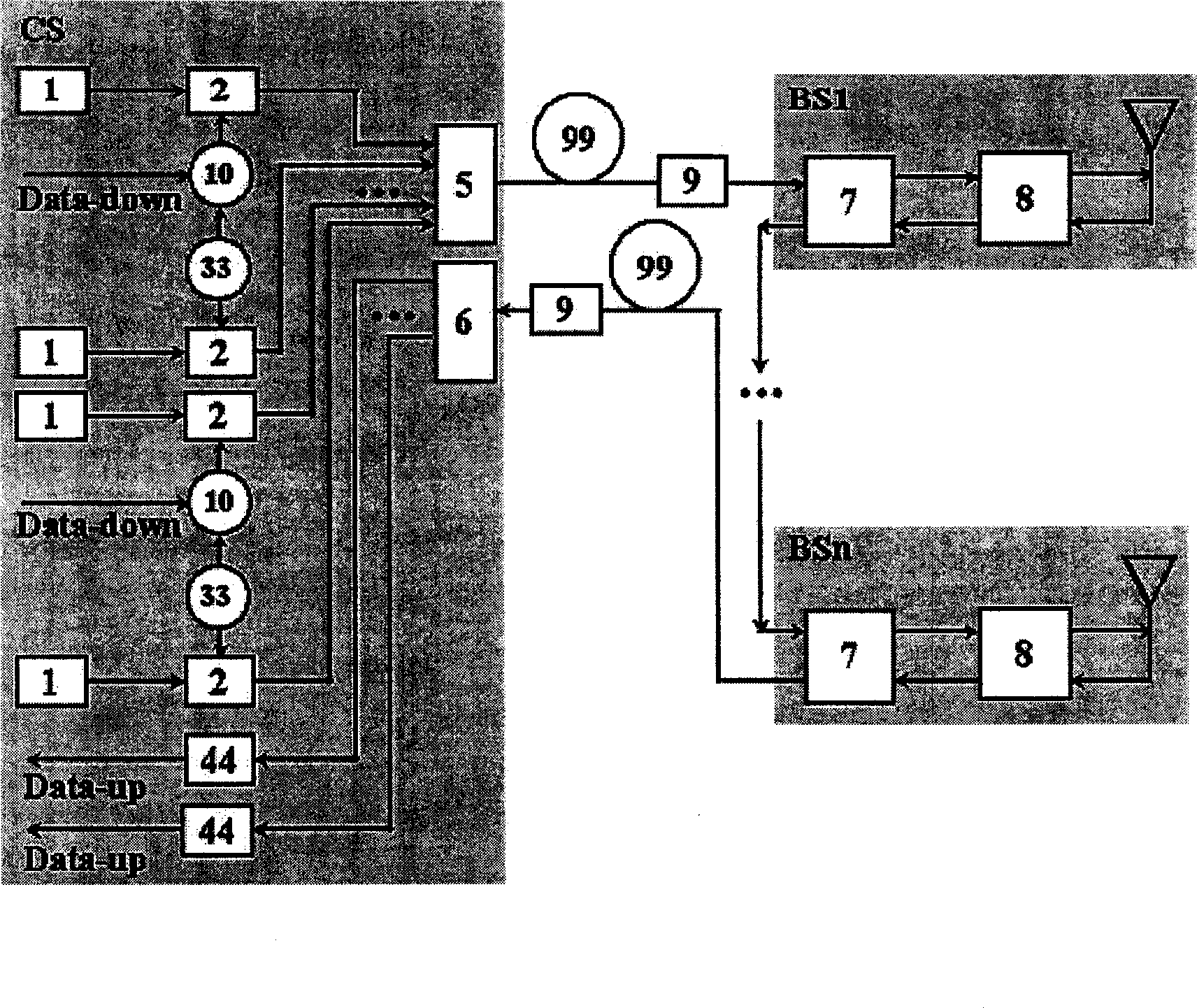
[0071] Such as figure 2 As shown, multiple main lasers with different wavelengths: 4, the wavelengths are in the ITU-standard channel, respectively: 1554.32nm, 1550.92nm, 1552.52nm, 1554.13nm; FP lasers: 4, the mode spacing is 50GHz; microwave oscillation Device: 25GHz (N=2); photoelectric modulator: 25GHz; can realize 50GHz millimeter wave 4-way wavelength division multiplexing light source array.

Embodiment 2

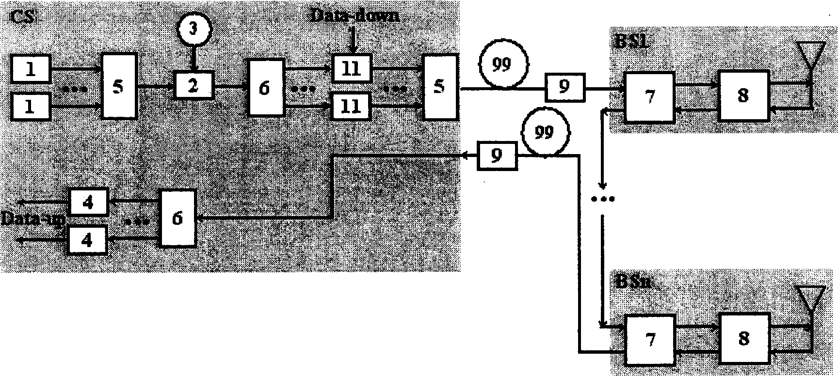
[0073] Such as image 3 As shown, the microwave oscillator: 25GHz (N=2); the SC light source produces 150 multimode outputs with a mode spacing of 25GHz in the 1510-1580nm band; FP lasers: 50, the mode spacing is 50GHz; The 1580nm band produces 50GHz millimeter wave 50 wavelength division multiplexing light source columns.

Embodiment 3

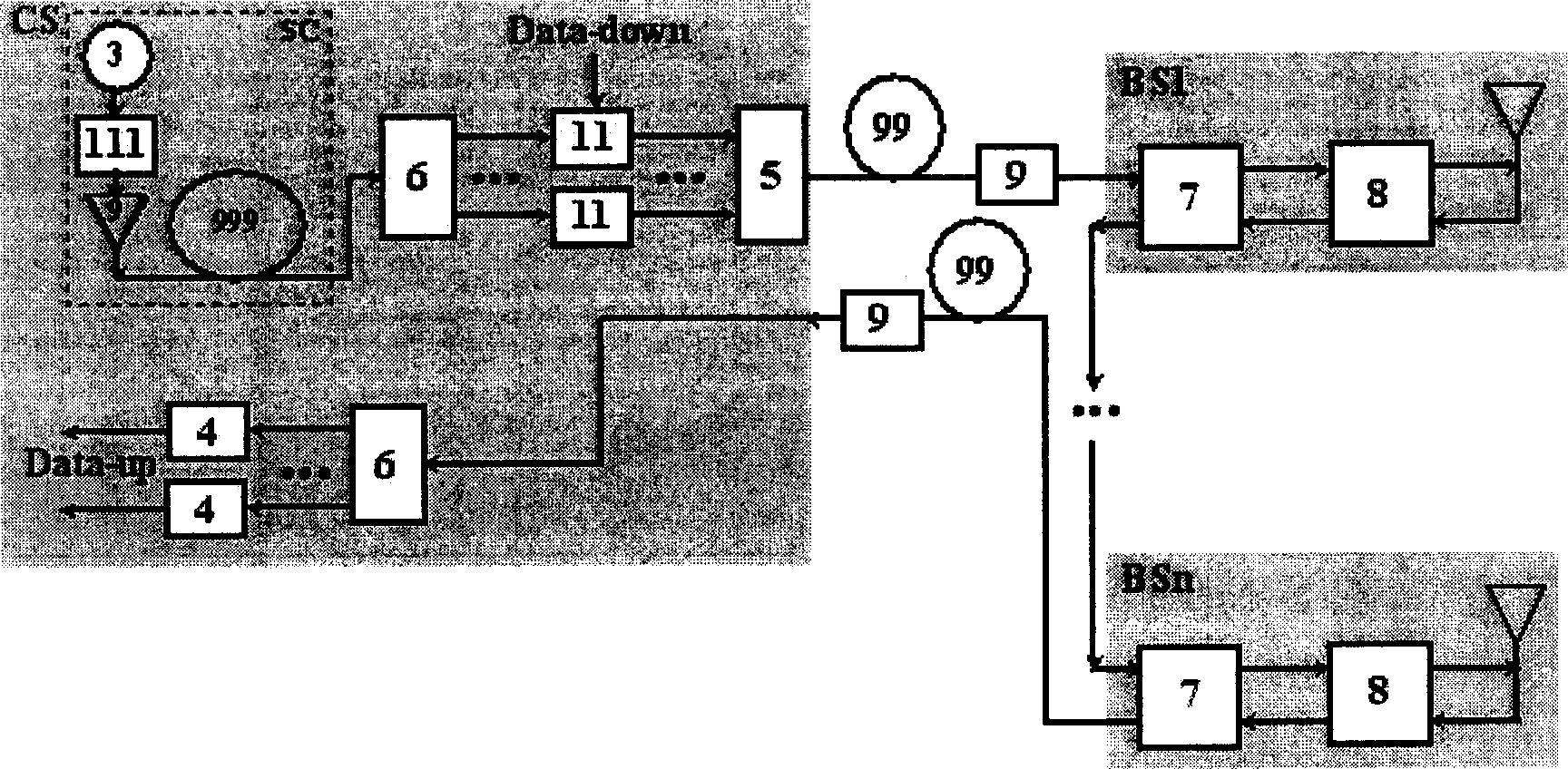
[0075] Such as Figure 4 As shown, microwave oscillator: 18GHz (N=3); OCG light source produces 100 multimode outputs with a mode spacing of 18GHz in the 1524-1540nm band; FP lasers: 25, with a mode spacing of 54GHz; The 1540nm band produces 54GHz millimeter wave 25-way wavelength division multiplexing light source array.


PUM


Abstract

Wavelength division multiplex millimeter wave light source row includes multiple wavelength comb type light signals generator, one optical demultiplexer, multiple multimode laser, and one multiplexer. The optical demultiplexer makes demultiplexing multiple wavelength comb type light signals. Multimode laser is input for each distributive wavelength segment. The multimode laser generates mode-locking light signals in dual mode with mode space in millimeter wave frequency. The multiplexer inputs mode-locking light signals in dual mode into optical fiber connected to base station after multiplexing. Under condition of shared microwave oscillator in frequency being as 1/N millimeter wave frequency and light signal modulator in same low frequency, the invention generates millimeter wave light source row by using harmonic modulation technique and mode locking dual mode technique. The invention makes cost for generating light signal in millimeter wave decrease greatly.

Description

Technical field: [0001] The invention belongs to the technical field of optical fiber transmission wireless signal (Radio-on-Fiber, abbreviated as ROF) communication system, and in particular relates to a wavelength division multiplexing millimeter wave light source array of an optical fiber transmission millimeter wave ROF wavelength division multiplexing communication system. Background technique: [0002] In recent years, Microwave Photonics (abbreviated as MWP) has developed rapidly. Taking advantage of the respective advantages of wireless communication and optical fiber communication, the "mobile ultra-large capacity ultra-high-speed" optical fiber transmission wireless signal (Radio-on-Fiber , abbreviated as ROF) communication system research work is increasingly given great attention. When the wireless signal is a millimeter wave, the ROF communication system is called a millimeter wave ROF communication system. [0003] The ROF wavelength division multiplexing comm...

Claims


Application Information

Patent Timeline
IPC IPC(8): H04B10/2575H04J14/02
Inventor 胡薇薇
Owner PEKING UNIV
Why Eureka
Try Eureka