Arc electrodes for synthesis of carbon nanostructures

A technology of carbon nanostructures and arc electrodes, applied in nanostructure manufacturing, nanotechnology for information processing, nanotechnology for materials and surface science, etc., can solve problems such as waste and low efficiency

Inactive Publication Date: 2004-03-03
SONY CORP
View PDF2 Cites 1 Cited by
  • Summary
  • Abstract
  • Description
  • Claims
  • Application Information

AI Technical Summary

Problems solved by technology

However, in order to prevent the tube from being melted, the process can only be carried out at about 1000°C
A large amount (up to about 90%) of the gas is therefore not utilized or wasted due to temperature constraints
Therefore, the process is very inefficient

Method used


Image

  • Arc electrodes for synthesis of carbon nanostructures
  • Arc electrodes for synthesis of carbon nanostructures
  • Arc electrodes for synthesis of carbon nanostructures

Examples


no. 1 example

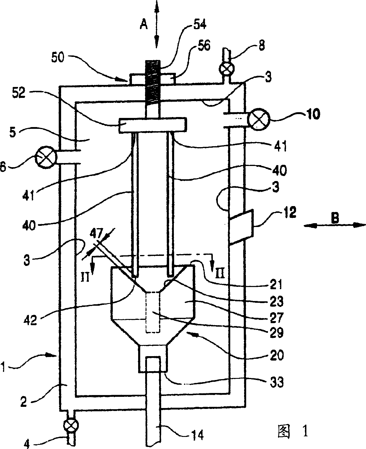
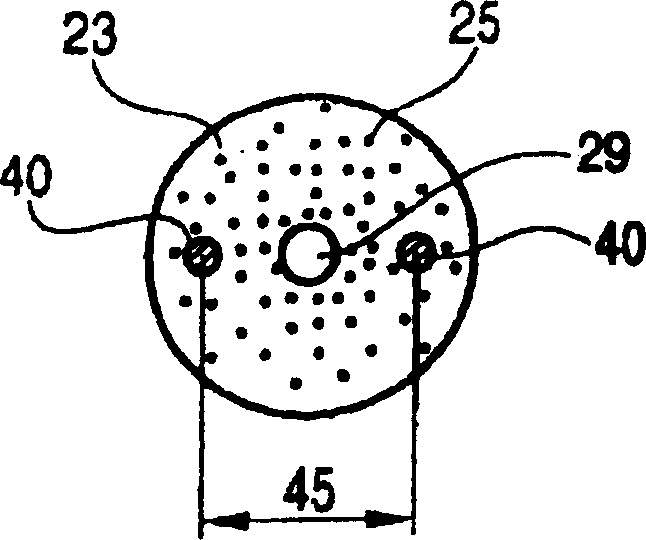
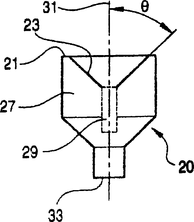
[0019] 1-3 show a first embodiment of the present invention. The device for manufacturing carbon nanostructures includes a chamber 1 , a first electrode 20 , or a plurality of second electrodes 40 , and an adjustment mechanism 50 .

[0020] The chamber 1 comprises a wall 2 surrounding a chamber interior 5 . Wall 2 is configured to allow cooling fluid to flow therethrough. A cooling fluid can be led through the cooling fluid inlet 4 and out of the cooling fluid outlet 8 in order to cool the chamber interior 5 . In addition, the chamber 1 comprises an inlet 6 and an outlet 10 so that a gas protective atmosphere can be formed inside the chamber interior 5 . A protective gas atmosphere includes any inert gas such as, for example, helium or argon. Additionally, the protective gas atmosphere may include hydrogen or a mixture of hydrogen and an inert gas, and is typically at a pressure of from about 300 Torr to about 760 Torr. The specific composition of the gas protective atmosp...

no. 2 example

[0045]A second embodiment of the invention is shown in FIG. 4 . Components that are the same as those illustrated and described in the first embodiment are given the same reference numerals, and therefore, descriptions of such components are omitted here.

[0046] In this embodiment of the invention, the chamber 1 comprises an outlet pipe 16 , a collection tank 18 , and a pump 19 . The outlet tube 16 is connected to the first electrode 20 and the collection tank 18 . The collection tank 18 is in turn connected to a pump 19 . Additionally, the first electrode 20 includes a central hole 29'

[0047] The interior of the chamber 5 is then in communication with the pump 19 so that by activating the pump 19 to generate a flow from the interior 5 of the chamber to the collection tank 18, the gas produced by the arc discharge between the first electrode 20 and the second electrode 40 can be easily removed. The produced carbon black is collected in collection box 18. The outfl...

no. 3 example

[0052] A third embodiment of the invention is shown in FIG. 5 . Components that are the same as those illustrated and described in the first and second embodiments are assigned the same reference numerals, and therefore descriptions of these components are omitted here. In this example, however, the carbon nanostructures are constructed from carbon components introduced in the gaseous state. That is, this embodiment is a CVD (Chemical Vapor Deposition) process.

[0053] The chamber 1 of this embodiment has an inlet tube 16' and a chamber outlet 10; the chamber inlet 6 is not required, but could be included if desired. That is, the introduction pipe 16' is connected to the central through hole 29' of the first electrode 20 and supplies gas to the arc plasma region and the chamber interior 5. An equal amount of gas exits the chamber 1 through the chamber outlet 10 in order to keep the pressure inside the chamber interior 5 constant during the arc discharge.

[0054] The carbo...


PUM

PropertyMeasurementUnit
diameteraaaaaaaaaa

Abstract

An arc electrode structure, for producing carbon nanostructures, which includes a first electrode and two or more second electrodes disposed within a chamber. The electrodes are connected to a voltage potential to produce an arc-plasma region. The first electrode has a sloped surface with a plurality of holes therein for holding catalyst. The first electrode's sloped surface, and the positioning of the plurality of second electrodes allows control of the direction and region of arc-plasma. Further, the first electrode has a central bore which may be either a blind bore, or a through bore. The blind bore collects unwanted deposits that slide off of the sloped surface of the first electrode. The throughbore either allows soot and carbon nanostructures to be removed from the chamber, or allows organic vapor to be introduced into the chamber. When the throughbore is used to introduce organic vapor into the chamber, the vapor is directed through the arc-plasma region so that carbon nanostructures are built up by a CVD process rather than being broken off of carbon electrodes.

Description

technical field [0001] The invention relates to an arc electrode structure for synthesizing carbon nanostructures and a method for manufacturing carbon nanostructures using the same. More specifically, the present invention relates to an electrode arrangement for generating arc plasma discharges for the synthesis of carbon nanostructures by consuming carbon-containing electrodes or by chemical vapor deposition (CVD) processes. Carbon nanostructures that can be produced include single-walled nanotubes (SWNTs), multi-walled nanotubes (MWNTs), fullerenes, endohedralmetallofullerenes, carbon nanofibers, and other carbon nanomaterials. Background technique [0002] In the related art, carbon nanostructures are fabricated using arc discharge between an anode and a cathode. For example, Japanese Patent No. 11-263609 published on September 28, 1999; D.T. Colbert et al., "Science of Fullerene Nanotubes" published on November 18, 1994, Science Magazine, Volume 266, can be found. Gr...

Claims


Application Information

Patent Timeline
Patent Type & Authority Applications(China)
IPC IPC(8): B82B3/00C01B31/02H01J37/32
CPCH01J37/3255B82Y10/00Y10S977/844H01J37/32532Y10S977/843B82Y30/00Y10S977/896H01J37/32055H01J37/32541C01B32/05B82B3/00H01J37/32
Inventor 黄厚金梶浦尚志宫腰光史山田淳夫白石诚司
Owner SONY CORP
Why Eureka
Try Eureka