Fistular cathodic axial powder feeding plasma painting gun

A plasma and spray gun technology, applied in arc spraying, liquid spraying device, spraying device and other directions, can solve the problems of difficult processing, low energy utilization rate and high cost, and achieve high energy utilization rate, simple structure and easy processing. Effect

Inactive Publication Date: 2004-03-17
INST OF MECHANICS - CHINESE ACAD OF SCI
View PDF2 Cites 7 Cited by
  • Summary
  • Abstract
  • Description
  • Claims
  • Application Information

AI Technical Summary

Problems solved by technology

The disadvantage of this spray gun is that: since the powder is sent into the plasma jet outside the nozzle, the high-temperature area of ​​the plasma is not fully utilized, and after the high-temperature plasma gas is sprayed from the nozzle, it is affected by the mixing of external air. At the same time, due to the dispersion of the particle size of the powder material, large particles can easily pass through the plasma jet, while small particles are not easy to enter the plasma jet, so the heating effect of the powder material is poor, and the energy utilization rate is very low. Low
This multi-cathode axial powder-feeding plasma spray gun has obvious improvements in improving energy utilization and coating quality, but it is obvious that it has disadvantages such as complex structure, difficult processing, and high cost, and requires three sets of power supplies Three cathode devices are supplied separately, which is inconvenient to operate and maintain

Method used


Image

  • Fistular cathodic axial powder feeding plasma painting gun
  • Fistular cathodic axial powder feeding plasma painting gun
  • Fistular cathodic axial powder feeding plasma painting gun

Examples


Embodiment Construction

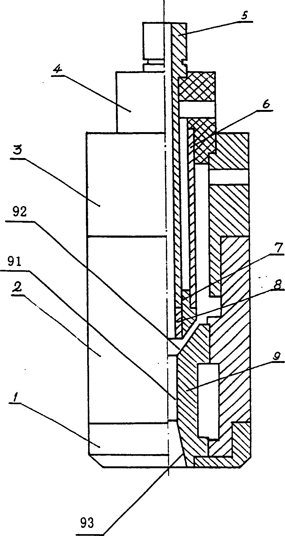
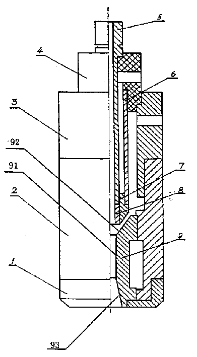
[0020] figure 2 Represents the structure of the axial powder feeding plasma spray gun of the embodiment of the present invention, which includes a compression nut 1, an anode body 2, an insulating sleeve 3, a cathode sleeve 4, a cathode powder feeding rod 5, a water guide sleeve 6, and a cathode seat 7 , cathode 8 and anode 9.

[0021] The cathode sleeve 4, the cathode powder feeding rod 5, the water guide sleeve 6, the cathode seat 7 and the cathode 8 constitute the cathode device, in which the cathode 8 and the cathode powder feeding rod 5 are both hollow tubular structures, and their axial directions are interpenetrating. The middle holes together constitute the powder feeding channel of the spray gun, and the diameter of the middle holes is selected as 3-6 mm. The cathode holder 7 is sleeved on the cathode for cooling the cathode 8, and the cathode and the cathode holder are replaceable. The cathode sleeve 4 is sleeved on the side of the cathode powder guide rod 5 close...


PUM

PropertyMeasurementUnit
diameteraaaaaaaaaa
lengthaaaaaaaaaa
diameteraaaaaaaaaa

Abstract

The present invention relates to one kind of axially powder-feeding plasma spray gun for improved plasma spraying technological process. The spray gun consists of water-cooled hollow cathode and tubular anode. The sprayed powder material is fed through the hollow cathode and heated in the high temperature area inside the spray gun to reach melt state gradually before leaving from the spray gun and being sprayed at high speed to the surface of the workpiece to be sprayed to form plasma coating with specific performance.

Description

technical field [0001] The invention relates to a plasma spraying gun, in particular to an axial powder feeding type plasma spraying gun. Background technique [0002] Plasma spraying is the use of electric energy to convert gases such as argon, nitrogen and hydrogen into high-temperature plasma jets, heat and accelerate powders such as metals, metal oxides and ceramics to be sprayed, and then spray them onto the workpiece. [0003] A common plasma spray gun has a rod-shaped cathode and a tubular anode, and the powder material to be sprayed is sent into the plasma jet from the radial direction at the outlet of the spray gun, see "Plasma Spraying of Metallic and Ceramic Materials", New York, 1989. The disadvantage of this spray gun is that: since the powder is sent into the plasma jet outside the nozzle, the high-temperature area of ​​the plasma is not fully utilized, and after the high-temperature plasma gas is sprayed from the nozzle, it is affected by the mixing of extern...

Claims


Application Information

Patent Timeline
Patent Type & Authority Applications(China)
IPC IPC(8): B05B5/06B05B7/14B05B7/22
Inventor 林烈吴彬
Owner INST OF MECHANICS - CHINESE ACAD OF SCI
Why Eureka
Try Eureka