Method and apparatus of semiconductor generating electricity and producing hydrogen using temperature difference and liquid natural gas providing cooling energy

A technology of liquefied natural gas and temperature difference power generation, applied in applications, home appliances, and other seating furniture, etc., can solve the problems of large power consumption, large cooling water consumption, and high cost of hydrogen production, and reduce power consumption costs and equipment costs , the effect of compact structure

Inactive Publication Date: 2004-03-31
UNIV OF SCI & TECH OF CHINA
View PDF2 Cites 24 Cited by
  • Summary
  • Abstract
  • Description
  • Claims
  • Application Information

AI Technical Summary

Problems solved by technology

In the prior art, when hydrogen is produced by electrolyzing water, the Joule heat generated by the current passing through the aqueous solution is not utilized, which consumes a lot of power; in addition, in order to take away the Joule heat,

Method used


Image

  • Method and apparatus of semiconductor generating electricity and producing hydrogen using temperature difference and liquid natural gas providing cooling energy
  • Method and apparatus of semiconductor generating electricity and producing hydrogen using temperature difference and liquid natural gas providing cooling energy
  • Method and apparatus of semiconductor generating electricity and producing hydrogen using temperature difference and liquid natural gas providing cooling energy

Examples


Embodiment 1

[0022] Example 1: Method and device for semiconductor thermoelectric power generation using LNG cold energy

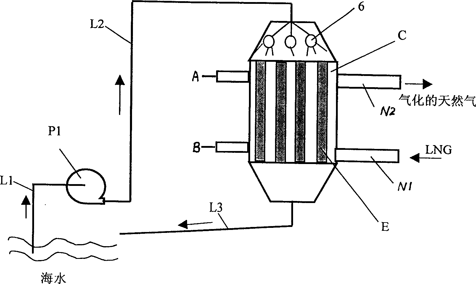
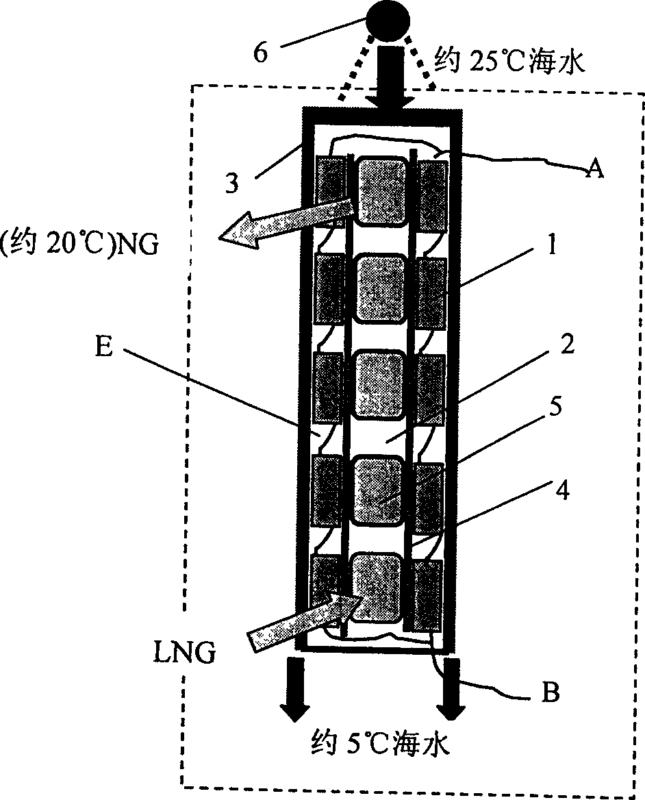
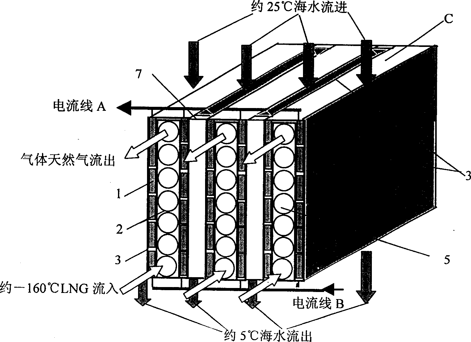
[0023] as attached figure 1 A schematic diagram of a device system flow chart of the method of semiconductor thermoelectric power generation using LNG cold energy is provided. The device system of this embodiment includes a semiconductor generator component C, a seawater pump P1, a seawater suction pipe L1, and a seawater delivery pipe L2 , seawater return pipe or channel L3, seawater spray pipe 6, LNG main inlet pipe N1 and gasification natural gas main outlet pipe N2, and current main incoming line A and main outgoing line B with protective tubes; the semiconductor generator assembly C consists of several The semiconductor generator unit E is combined. The structure of the semiconductor power generation unit E is as attached figure 2 As shown, the cold source heat exchanger adopts a plate-tube structure, and the metal plate 4 is made of an aluminum or copper plate...

Embodiment 2

[0026] Example 2: Using liquefied natural gas cold energy semiconductor temperature difference to generate hydrogen

[0027] Figure 4 It is a schematic diagram of the principle of a specific implementation of a hydrogen production device using LNG cold energy semiconductor thermoelectric power generation. It includes a semiconductor thermoelectric generator assembly and an electrolyzed water hydrogen production device. The semiconductor thermoelectric generator assembly in this embodiment is divided into two groups according to the temperature of the cold and heat sources: one group BD1 is drenched with normal seawater, and the other group BD2 is drenched with high temperature seawater that recovers waste heat from hydrogen production. In the electrolyzed water hydrogen production device H, the hydrogen side of the electrolytic cell D is sequentially connected to the hydrogen-gas-liquid separator F1 and the hydrogen-cooled water vapor condenser Y1; the oxygen side of the ele...


PUM


Abstract

A method of generating electricity and preparing hydrogen taking advantage of difference in temperature of semiconductors. It is characterized in, the semiconductor genertrix by thermal difference iscomposed of cold or heat surfaces of a thermopile closely contacting with cooling-source heat exchanger with LNG flowing, and heating-source heat exchanger with sea flowing. While heating LNG, the semiconductor genertrix by thermal difference produces direct currents; connecting the power with anode and cathode of an electrobath, water is electrolyzed into hydrogen and oxygen; some seawater firstcools the alkali liquor of electrolyzed water, then is transmitted to the heating-source heat exchanger. Sea water provides cooling water when preparing hydrogen, as well as provides heating source of LNG, which improve efficiency of semiconductor; electricity produced in recycling LNG could be used to prepare hydrogen, which saves the area of heat exchanger and cooling water for preparing hydrogen.

Description

Technical field: [0001] The invention belongs to the technical field of energy, in particular to the cross technical field of recycling and utilization of liquefied natural gas (LNG) cold energy, semiconductor thermoelectric power generation and hydrogen production by electrolysis of water. Background technique: [0002] With the rapid development of semiconductor technology and the continuous availability of various high-quality semiconductor materials, semiconductor refrigeration technology has made great progress, and semiconductor thermoelectric power generation technology has attracted great attention and has many practical examples. According to Seebeck's principle, when there is a temperature difference between the two ends of the contact between the P-type and N-type semiconductors, an electromotive force will be generated in the loop, which is also called thermoelectric potential, and a potential difference will be generated across the open circuit of the loop. Curr...

Claims


Application Information

Patent Timeline
IPC IPC(8): A47C21/04
Inventor 陈则韶程文龙胡芃
Owner UNIV OF SCI & TECH OF CHINA
Why Eureka
Try Eureka