Magnetic-driven axial-flow auxiliary pump for heart

A heart-assisted, axial-flow technology, used in medical science, prostheses, etc., can solve problems such as wear, thinning of aortic wall structure, infection, etc.

Inactive Publication Date: 2004-04-14
张杰民 +1
View PDF0 Cites 8 Cited by
  • Summary
  • Abstract
  • Description
  • Claims
  • Application Information

AI Technical Summary

Problems solved by technology

The traditional axial flow pump cannot solve the problem of damage to the blood and coagulation mechanism caused by cutting blood during the rotation of the blades
[0005] Commonly used heart assist devices can lead to various bacterial and even fungal infections, thrombosis, destruction of blood and blood vessels, and decreased immune function
Long-term use of axial flow pumps for advective p

Method used


Image

  • Magnetic-driven axial-flow auxiliary pump for heart
  • Magnetic-driven axial-flow auxiliary pump for heart
  • Magnetic-driven axial-flow auxiliary pump for heart

Examples


Embodiment Construction

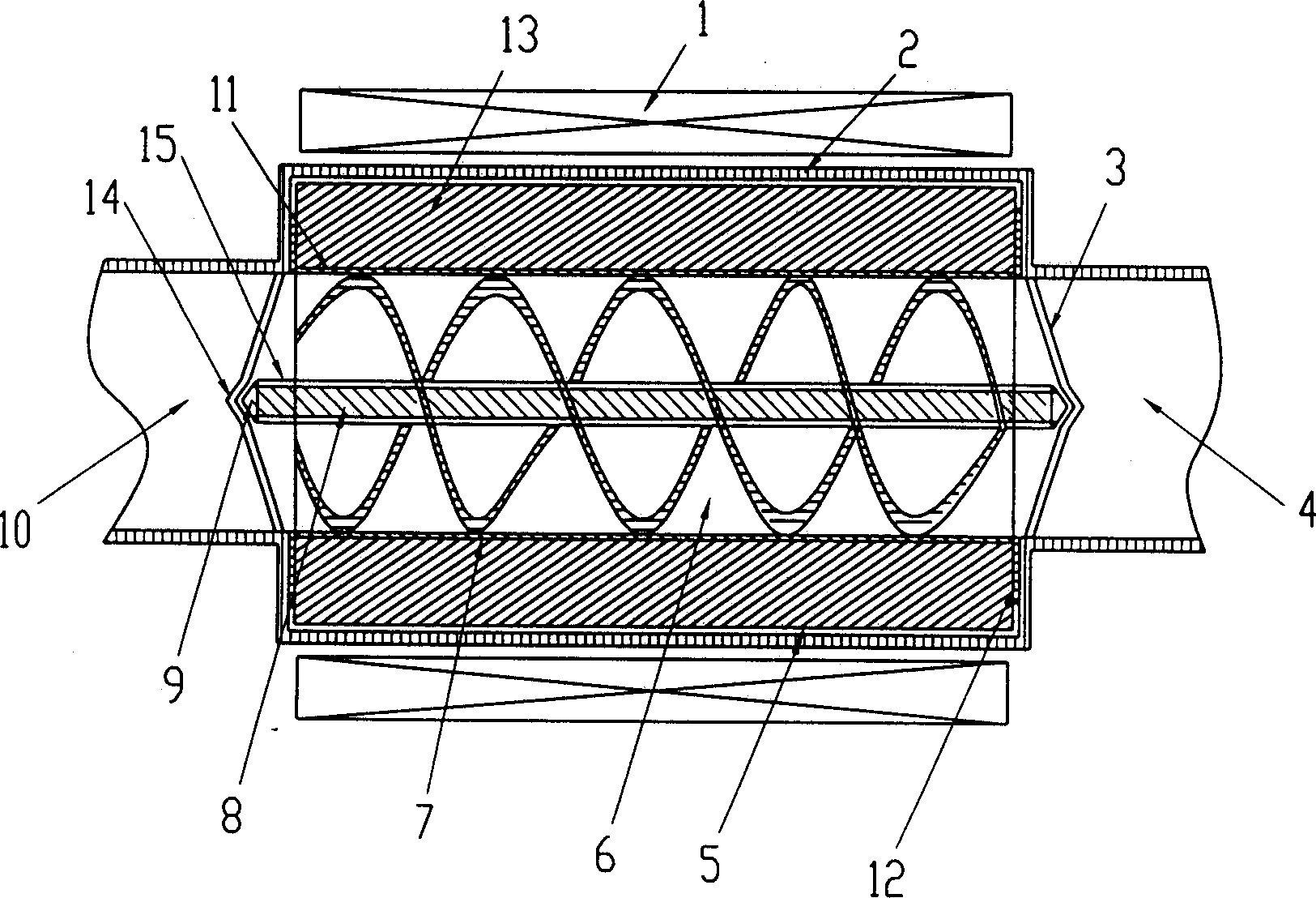
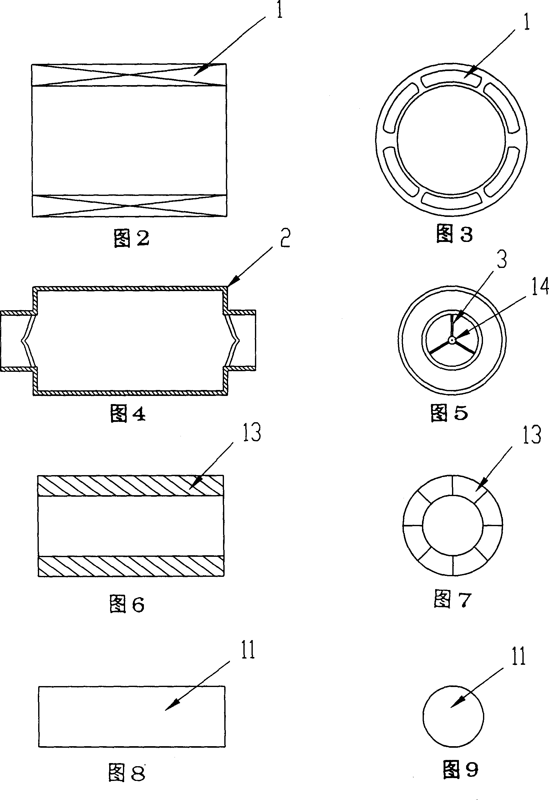
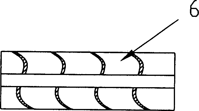
[0033] The magnetically driven axial flow blood pump of the present invention includes: (1) stator windings wound around a cylindrical stator housing; (2) a centrally enlarged cylindrical rotor positioned at the center of the axial flow pump; (3) a permanent magnet The rotor consists of 8 radially arranged magnetic materials. (4) Double helical blades are fixed on the inner surface of the permanent magnet rotor; (5) A central axis is fixed on the center of the entire rotor; (6) The permanent magnet rotor and the outer casing are separated from the blood by a sealing gasket to form a minimum air gap. (7) Both ends of the central shaft cooperate with the bushing at the center of the cantilever of the stator to form a magnetic levitation rotor.

[0034] Specific embodiments of the present invention can be found in Figure 1 to Figure 12 . figure 1 It is a structural schematic diagram of the present invention, which includes three components: a stator 1, a rotor, and a DC stabil...


PUM


Abstract

The invention discloses a magnetic dive axial-flow heart assistant pump, composed of stator, rotor, and DC voltage-stabilized power supply. The stator comprises stator winding and stator casing and the rotor composed of tube high-energy level magnet and propelling equipment. The propelling equipment integrated composed of internal sleeve, central shaft and two impeller blades to develop a spiral sealed blood propelling channel; the rotor is placed in the subulate shaft sleeve of stator cantilever. The stator winding generates magnetic field to drive the rotor to put the blades in motion, makes the blood one-way flow and assists or completely replaces the heart to pump blood. The stator winding is connected with the power supply.

Description

technical field [0001] The present invention relates to a heart assist pump. Background technique [0002] During nearly half a century of research on cardiac assist devices, their materials, structures, manufacturing processes, functions, and service life have been continuously improved and developed, and different drive methods such as pneumatic, electric, and electro-hydraulic have emerged. The blood flow is also closer to the physiological heart. Cardiac assist devices are an important means of maintaining life in critically ill patients. It is divided into three ways: final replacement, waiting for transplantation, reducing cardiac load, and promoting functional recovery. [0003] With the continuous development of medical science, there are more and more patients with acute heart failure, unable to leave the cardiopulmonary bypass machine after cardiac surgery, and waiting for heart transplantation. They urgently need cardiac assistance for short-term transition or l...

Claims


Application Information

Patent Timeline
IPC IPC(8): A61M1/10
Inventor 张杰民万峰
Owner 张杰民
Why Eureka
Try Eureka