Combined sealing piston ring

A sealing piston and combined technology, which is applied in the field of piston rings, can solve the problems of trapezoidal inclined surface processing of trapezoidal inclined surface split rings, affecting the service life of piston rings, affecting the service life of cylinders, etc., to achieve fuel saving, uniform thickness, and service life prolonged effect

Inactive Publication Date: 2004-04-14
徐楠
View PDF4 Cites 2 Cited by
  • Summary
  • Abstract
  • Description
  • Claims
  • Application Information

AI Technical Summary

Problems solved by technology

Its disadvantages are: because the piston ring works in a high-temperature and high-pressure environment, and the gas shock and mechanical vibration generated during work will cause the positioning pin or pin to fall off, once the positioning pin or pin falls off, it will cause serious damage to the engine, and its processing and assembly relatively troublesome
Its disadvantage is: because the joint surface of the two rings is an inclined plane, when the piston ring is working, due to the working pressure and mechanical vibration, the two rings will be relatively offset, so that the actual shape of the two rings is round and waist-shaped, which is in line with the cylinder wall. It is easier to rub it into an ellipse when rubbing, which affects the service life of the cylinder. In this way, the gain outweighs the loss, and the trapezoidal bevel processing of the trapezoidal bevel split ring is also very difficult
Its disadvantage is that, in order to prevent the relative rotation of the two sub-rings, the above two schemes adopt the design of the joint shoulder surface as either an ellipse or an eccentric circle, and the thickness of the shoulders of the two rings is different, resulting in the entire ring The strength is reduced, and deformation is easy to occur. Once deformation occurs, the sealing effect will deteriorate, the air tightness will be reduced, the purpose of use will not be achieved, and the service life of the piston ring will be affected. At the same time, the processing of the above two technical solutions is relatively complicated.

Method used


Image

  • Combined sealing piston ring
  • Combined sealing piston ring
  • Combined sealing piston ring

Examples


Embodiment Construction

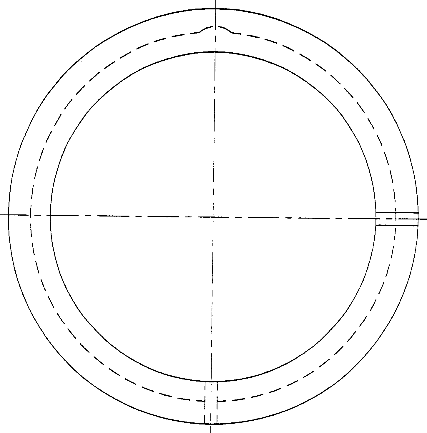
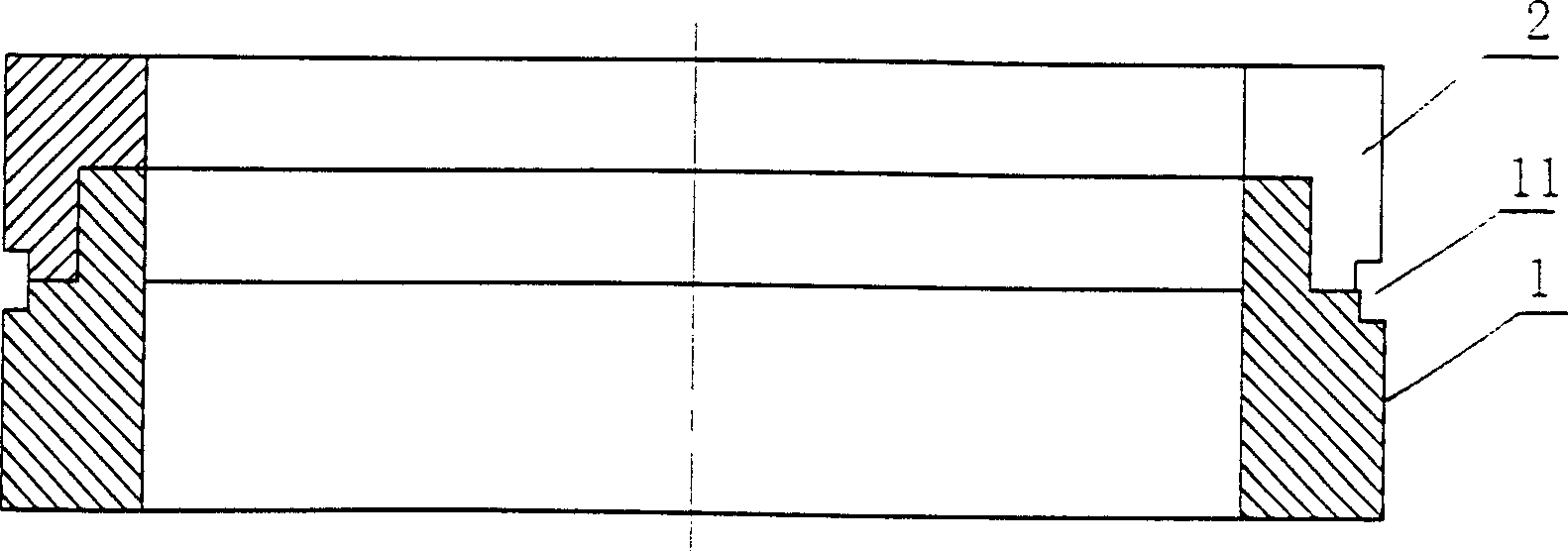
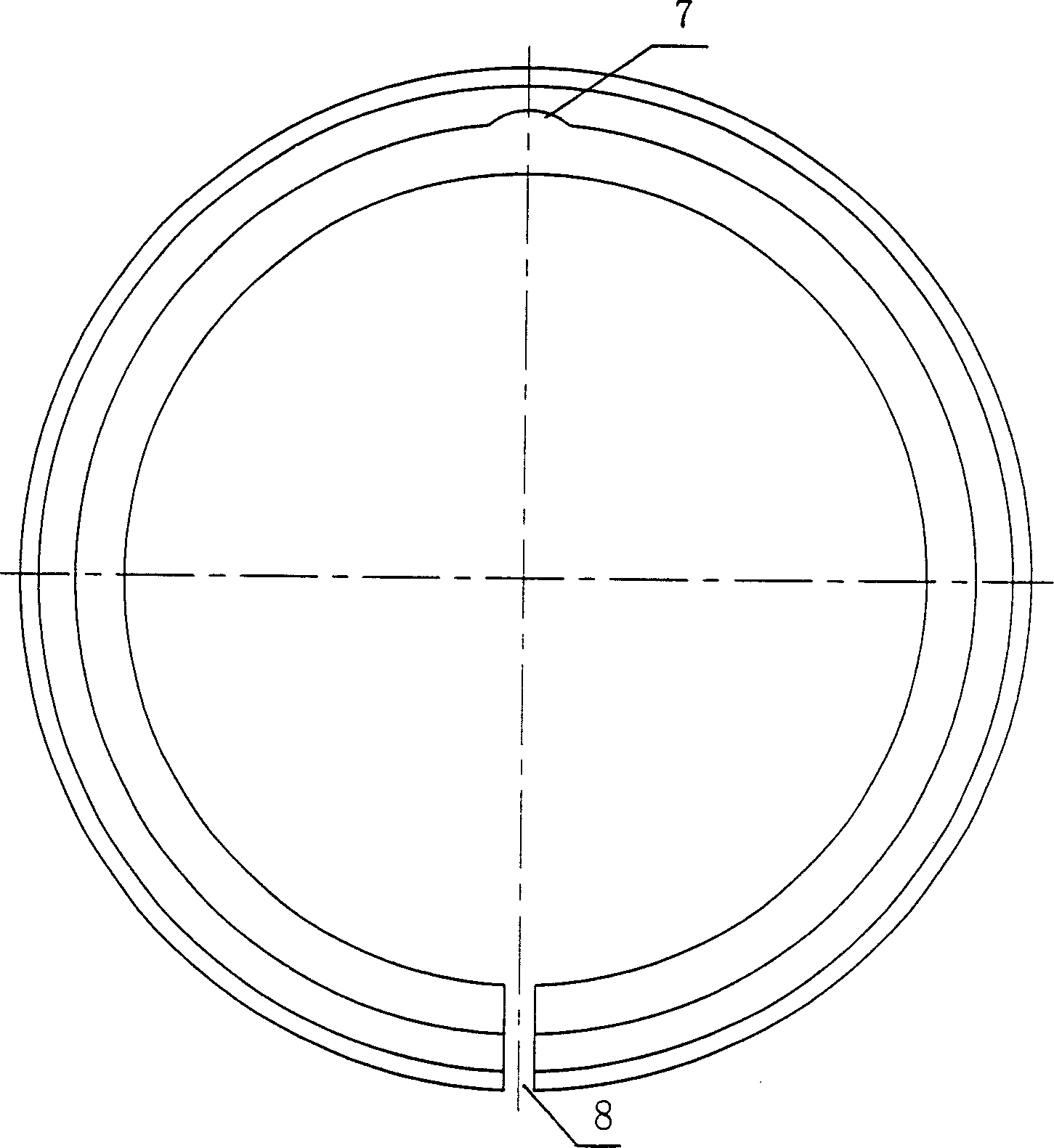
[0038] attached Figure 1~6 It is the accompanying drawing of the first embodiment of the present invention.

[0039]In the accompanying drawing, the combined piston ring includes sub-ring I1 and sub-ring II2 with the same thickness. Both sub-ring I1 and sub-ring II2 have openings. There is a concave shoulder 3 on the sub-ring II2. The circumferential surface of the concave shoulder 3 is in line with the The inner and outer circles of the sub-ring II2 are concentric, and there is a slightly concave arc-shaped depression 4 on the inner concave shoulder 3, and the depression is at an angle of 180° to the opening 5 on the sub-ring II2, and there is an outer convex shoulder 6 on the sub-ring I1, The peripheral surface of the outer convex shoulder 6 is concentric with the inner and outer circles of the sub-ring I1, and the outer convex shoulder 6 has an arc-shaped protrusion 7 whose shape matches the depression 4 on the inner concave shoulder of the sub-ring II2. 7 and the opening ...


PUM


Abstract

The present invention relates to a combined packing piston ring used in the piston machines of internal combustion engine and air compressor, etc. Said combined packing piston ring includes subring A and subring B, said two subrings have open-end respectively. Said invention also provides the assembly method of said two subrings and concrete steps. The adoption of said invention can raise cylinder compression ratio, can make full combustion, raise power of internal combustion engine, save fuel oil and can prolong the service life of piston ring.

Description

Technical field [0001] The invention relates to a piston ring, in particular to a combined sealing piston ring used in piston machines such as internal combustion engines and air compressors. Background technique [0002] Because the traditional piston ring works in a high temperature and high pressure environment, there is an opening on the piston ring to prevent it from being stuck in the cylinder groove after being heated and expanded, resulting in cylinder scuffing. But in this way, when the internal combustion engine works, gas will enter the gap between the cylinder wall and the piston from the combustion chamber and then enter the next chamber from the opening, so the opening of the piston ring becomes the main channel for leakage, and is also the channel for blowing oil. According to the "Piston Ring" published by Railway Press, "for a general internal combustion engine, the air pressure is 25% of the original after the first ring, 10% after the second ring, and 5% a...

Claims


Application Information

Patent Timeline
Patent Type & Authority Applications(China)
IPC IPC(8): F02F5/00F16J9/00
Inventor 徐楠
Owner 徐楠
Why Eureka
Try Eureka