

Polishing mattress and multilayer polishing mattress
A polishing pad and polishing layer technology, which is applied in the direction of electrical components, circuits, abrasives, etc., can solve the problems of not being able to suppress clogging, not being able to uniformly distribute the slurry, and not being able to increase the polishing speed, so as to achieve excellent flatness, scratch suppression, and effective polishing Effect
- Summary
- Abstract
- Description
- Claims
- Application Information
AI Technical Summary
Problems solved by technology
Method used
Image

Examples
Embodiment 1-1
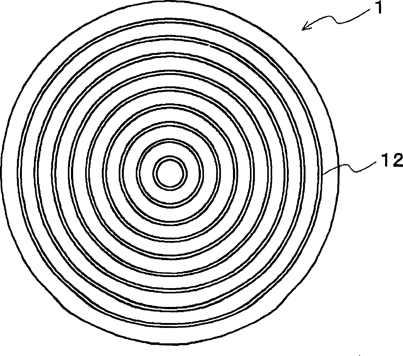
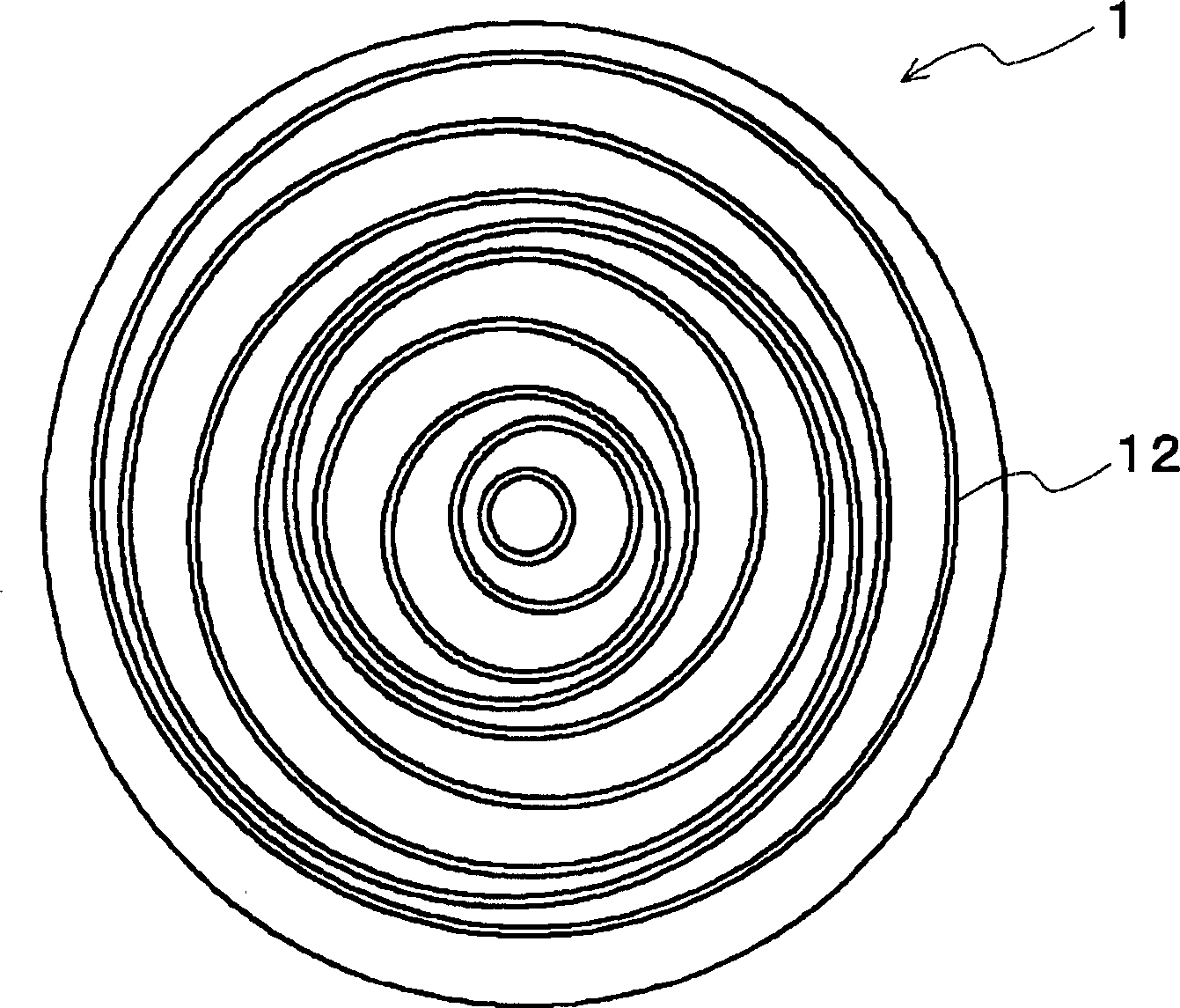
[0128] Using a screw extruder temperature adjusted to 160°C, 80 parts by volume of 1,2-polybutadiene (manufactured by JSR Corporation, trade name "JSR RB830") forming a cross-linked water-insoluble matrix and 20 parts by volume of β-Cyclodextrin (manufactured by Yokohama International Institute of Biological Research Co., Ltd., trade name "Dexipearl β-100", average particle diameter: 20 µm) which itself is water-soluble particles was kneaded to obtain white particles. Then add 0.3 parts by volume of an organic peroxide (manufactured by NOF Co., Ltd., trade name "Percumyl D-40"), further knead at 120°C, and then extrude the kneaded mixture into a metal mold and heat at 170°C It was cross-linked for 18 minutes to obtain a disk-shaped molded body with a diameter of 60 cm and a thickness of 2.5 mm. Then use a cutting machine (manufactured by Kato Machinery Co., Ltd.) to process concentric circular grooves (see figure 1 ).
[0129] Next, the surface roughness (Ra) of the inner surf...
Embodiment 1-2
[0132] With a screw extruder temperature adjusted to 160°C, 100 parts by volume of 1,2-polybutadiene (manufactured by JSR Corporation, trade name "JSR RB840") and 100 parts by volume of Water-soluble particles (average particle diameter: 20 μm) formed by coating a polypeptide on β-cyclodextrin (manufactured by Yokohama International Institute of Biological Research Co., Ltd., trade name “Dexipearl β-100”) were kneaded to obtain white particles. Then, 0.3 parts by volume of an organic peroxide (manufactured by NOF Corporation, trade name "Perhexine 25B") was added to the white granules, followed by further kneading at 120° C. to obtain white granules. Further, the white particles added with organic peroxide were put into a metal mold and heated at 190° C. for 10 minutes to cross-link to obtain a disk-shaped molded body with a diameter of 60 cm and a thickness of 2.5 mm. Then use the same cutting machine as in Example 1-1 to form concentric circular grooves with a width of 0.5 m...
Embodiment 2-1
[0151] With cutting machine (manufactured by Kato Machine Co., Ltd.) on one side of the disc-shaped molded body with a diameter of 60 cm and a thickness of 2.5 mm obtained in Example 1-1, form a structure with a width of 0.5 mm, a depth of 1 mm, and a longitudinal spacing of 5 mm. The horizontal spacing is 5mm, and the grid pattern is a square grid groove (see Figure 4 ).
[0152] Furthermore, a sheet for measuring surface roughness (Ra) was cut out from the obtained polishing pad along the direction including the width of the groove. Then, the surface roughness (Ra) and the like of the inner surface of the groove were measured in three different fields of view using the above-mentioned three-dimensional surface structure analysis microscope. As a result of the measurement, the surface roughness (Ra) was 2.5 μm.
[0153] Then use an optical microscope to enlarge and photograph the cross-section of the grooved portion of the polishing pad. The resulting image is shown in ...
PUM
 Abstract
Description
Claims
Application Information